A1
10V GND E1 D1
11 14
Open-Collector Out
DC Out
Analog In
Digital In
ECblue (_ _ _ _ _-_I_.B_._ _ _ _) (_ _ _ _ _-_I_.D_._ _ _ _)
EMUN19K0
08.06.2021
K1
max. AC 250 V 2 A
Signal
0...10 V
0...100 % PWM
+
7 6
2
10 kΩ
L1NPE
RD
BU
YE
GN
WH
BK
BN
WH
WH
GNYE
BU
BN
Netzspannung Leistungsschild
Line voltage Rating-plate
1
A
(D+)
B
(D-)
8
MODBUS
(RS-485)
4
3
5
1 Line voltage
rating plate
2 Relay output for fault indication (contact rating max. AC 250 V 2 A)
3 MODBUS (RS-485) interface
4 Open-Collector output status / tacho (I
max
20 mA)
5 Digital input for enable (R
i
approx. 2 kΩ)
6 Input for speed setting by 0...10 V signal / potentiometer (R
i
> 100 kΩ)
7 Voltage supply 10 V DC (I
max
50 mA)
8 Version with connection cables
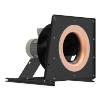
Assembly instructions ECblue Enclosure
L-BAL-F055D-GB 2021/51 Index 006 Part.-No.
50/56

 Loading...