Information
•
Pay attention to a sufficient screw-in length in the motor flange.
•
An excess screw length of max. 3 mm is permissible.
•
Every screwing case is different. The tightening torque adapted to it must be determined by the
appropriate screw tests.
•
In the case of a vertical motor axis, the respective lower drain hole must be open.
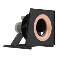
Ensure that the clearance (gap) “a” see fig. between
the fan impeller and the stationary housing section is
constant. Distortion due to uneven surface may lead to
fan failure.
Attention!
•
Avoid structural damage or stress with installation. Flange and mounting bracket must be fixed flat
on a level surface.
•
The fan must be securely mounted, with vibration dampers if necessary.
4.7.2 Mounting of centrifugal fans design RG.. / RD..
Fastening depending on housing design on flange or fastening brackets.
Information
An additional bracket is required for fastening to the flange. This is available as an accessory.
Attention!
•
Avoid structural damage or stress with installation. Flange and mounting bracket must be fixed flat
on a level surface.
•
Provide screwed connections with suitable screw locking.
4.7.3 Erecting the equipment: Design ER.. / GR.. / WR..
•
To avoid the transference of disruptive vibrations, we recommend de-coupling the entire plug fan to
avoid sounds transmitted through solids. (Spring and/or attenuation units are not a constituent part
of the standard scope of delivery). Look at our catalogue for positioning the decoupling elements or
request a dimensions sheet stating the type designation and Part.-No.
•
Erect in the open air only if this is expressly mentioned and confirmed in the ordering information.
There is a risk of damage to the bearings if the fan remains stopped in a moist environment. Avoid
corrosion by suitable protective measures. Roofing is required.
•
In the case of a vertical motor axis, the respective lower drain hole (if available) must be open.
•
The GR design in position “H” (horizontal shaft) should be installed in the preferred direction. The
cable guides should point downwards (angled sideways by approx. 30°). This is indicated by the
“OBEN/TOP” warning sign on the device.
•
Design ER.. / WR.. is only permissible with horizontal motor shaft.
Attention!
•
All contact points must be fixed securely. If the fixing is inadequate there is a risk of the fan
overturning.
•
Making your own alterations/conversions on the fan module is unacceptable - safety risk.
Design WR: maximum permissible number for installing several fan units on top of one another
Size External dimensions [mm] Permissible number
1 607 x 607 5
2 760 x 760 5
3 912 x 912 5
Assembly instructions ECblue Mounting
L-BAL-F055D-GB 2021/51 Index 006 Part.-No.
14/56

 Loading...