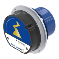
1 Cover for terminal compartment
2 Cable glands (2 x M16x1.5)
seal insert with two holes 5 mm for two cables applicable if necessary
3 Do not loosen the safety screws from the housing!
4 Connection control system
5 Connection alarm relay and voltage supply
6 Status LED
Procedure:
1. Remove the cover from the terminal compartment for the connection.
2. Both cable entry points are in a sealed condition at delivery.
– Turn in cable gland until seal breaks.
– Unused entry points must be sealed!
3. Insert and connect cables properly and ensure tightness of the cable glands.
4. Attach connection cover again carefully in correct position before start-up.
Information
The seal of the end cap can adopt the contour of the housing in time.
Therefore mount the cover on the same motor that it was removed from to achieve maximum
tightness.
Attention!
•
Temperatures up to 80 ° C can be present on the controller housing.
•
To connect, always use heat resistant wires or, as an alternative, silicon tubes.
•
Only use lines which can guarantee a permanent seal around the cable glands (pressure-resistant,
dimensionally-stable, round-centred jacket; e.g. by means of gusset filling)! Lines with filling fleece
are not permissible because moisture can penetrate due to the capillary effect!
•
Two lines may only be fed through one cable gland with the sealing insert for two lines.
•
When using the seal insert for two cables it is not permissible to use the corresponding cable gland
with only one cable.
•
Make absolutely sure that different connections do not come into contact (e.g. by splaying or loose
connecting wires).
•
Remants from installation and foreign object may not remain on the inside!
Assembly instructions ECblue Electrical installation
L-BAL-F055D-GB 2021/51 Index 006 Part.-No.
17/56

 Loading...