806834 v1.02 07.21 G5 Online install instructions and user guide
20
SAFETY
INSTALLATION
TROUBLE
SHOOTING
COMMISSION
USER GUIDE
TAP SAFETY
LCD SCREEN
CONTACT
INSTALLATION
GUIDE
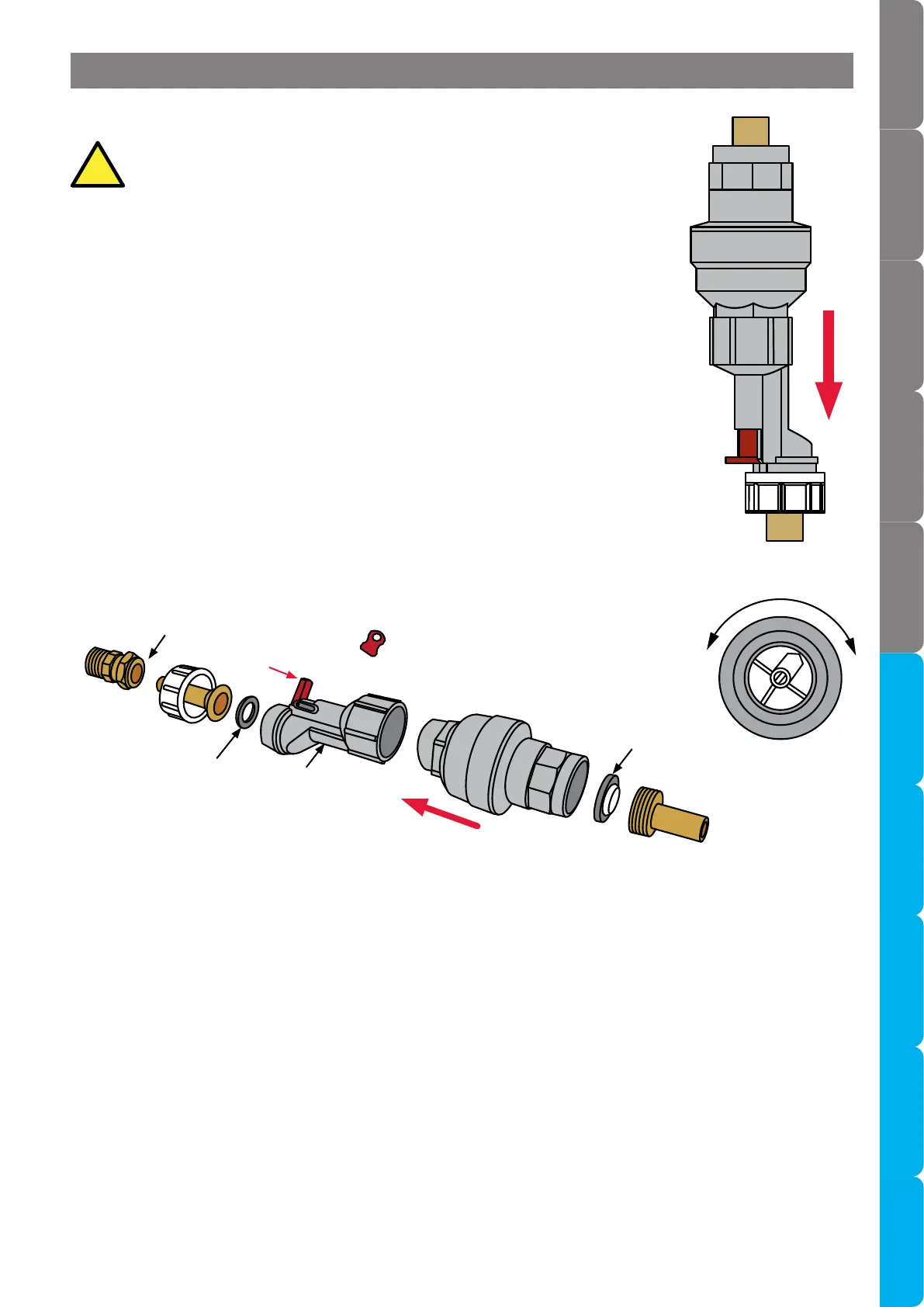
This device must be installed vertically with the direction of flow
downwards (inlet at the top , outlet at the bottom. See Fig 1 adjacent).
• The Water Block should be installed in a convenient location on the water supply
line to the Zip product.
• Pointer ‘P’ (see Fig.3) should be rotated until in line with the maximum required
flow at one time. Each number on the scale corresponds to 5 litres of flow i.e. 1 =
5 litres, 10 = 50 litres.
• The adjustment key (see Fig.2) should be used to adjust the pointer.
• The inlet should be connected via an 15mm isolation valve (not supplied).
• The outlet shall be connected via the 15mm - 1/2” brass compression fitting
supplied.
• Ensure that the direction of flow through the Water Block is correct and that
the filter screen (see Fig.2) is inserted correctly with the convex surface facing
towards the water supply.
3.2.1 Installation
Fig. 2
Fit key to adjust flow
Reset lever
3.2.2 Reset Procedure
• The Water Block will activate and shut off the supply if more water than the set amount is drawn off at one
time.
• In this event firstly isolate and de-pressurise the water supply to the Water Block, identify and repair the
cause of the leak then remove the pipe-work downstream of the Water Block and press the reset button
‘H’ (see Fig.3).
• The reset device (see Fig.2) may be fitted to avoid disconnection. This allows the Water Block to be reset
by operating the lever in the direction shown in Fig.2.
• In the event of persistent tripping contact Zip for advice.
3.2.3 Maintenance
• The filter screen should be checked and cleaned periodically subject to water conditions and usage.
Fig. 1
Fig. 3
Direction of flow
Seal
Reset
device
Direction of
flow
Filter
screen
15mm - 1/2” brass com-
pression fitting
0
1
2
3
4
5
6
7
8
9
Section 3.2 Water Block installation (optional accessory)