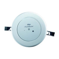
806834 v1.02 07.21 G5 Online install instructions and user guide
25
SAFETY
INSTALLATION
TROUBLE
SHOOTING
COMMISSION
USER GUIDE
TAP SAFETY
LCD SCREEN
CONTACT
INSTALLATION
GUIDE
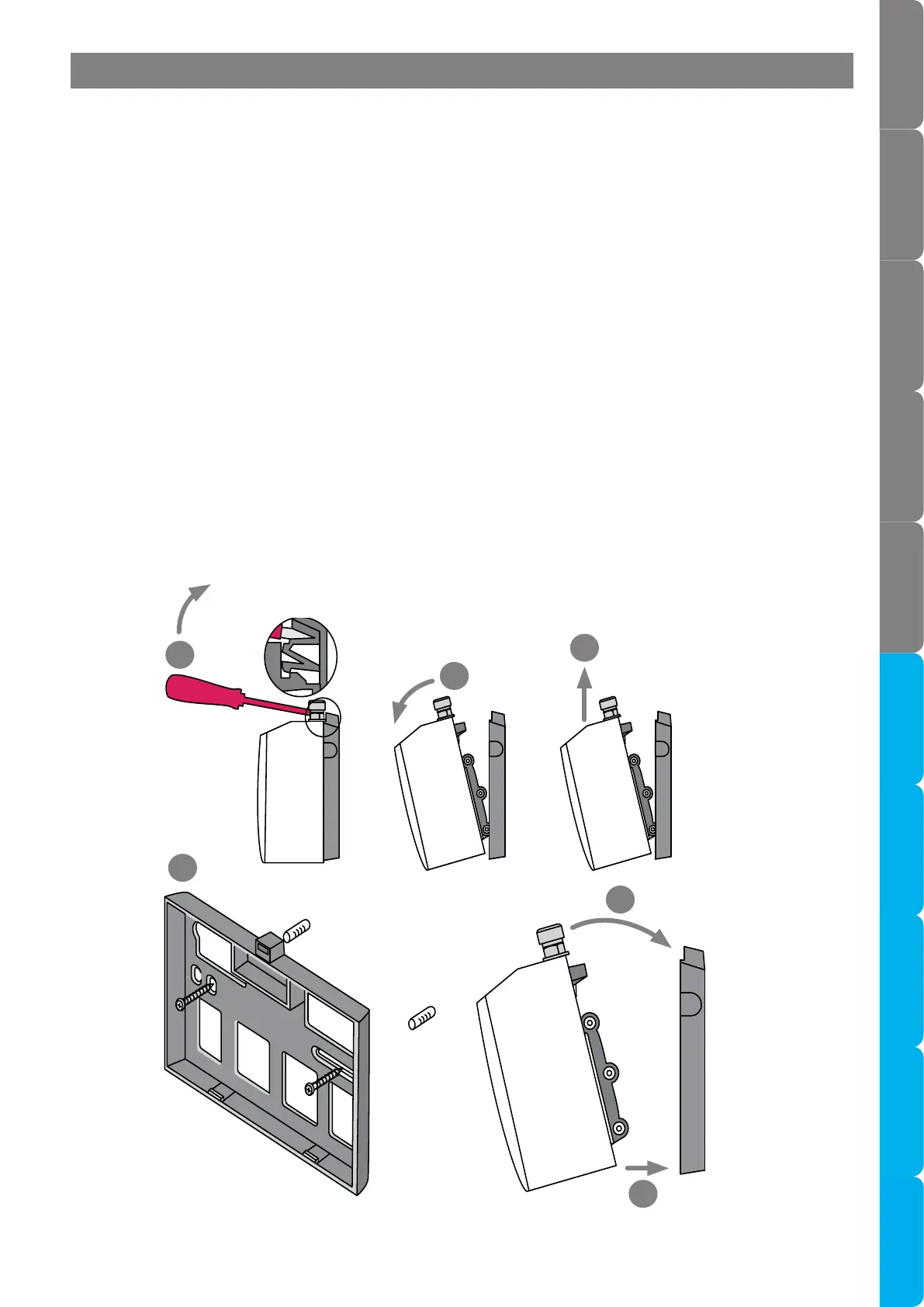
3.6.2 Installation procedure
Site requirements
• Booster must only be installed in a frost-free area. Never expose booster to frost.
• The booster is designed for wall mounted installation and must be installed with water connectors facing
upwards.
• The booster is protected against water ingress to class IP 25.
• The braided hoses supplied with the booster cannot be lengthened.
• The 90° elbow hose ends should be fitted to the inlet and outlet connections on top of the booster.
• The hot water outlet hose must be thermally insulated with the insulation provided.
Note Remove the wall mounting chassis from the rear of the booster for wall mounting.
Note Take care not to break the lower clips when removing or installing the booster.
3.6.3 Booster installation see diagrams below
• To remove the mounting chassis, insert a flat blade screwdriver all the way into the lock.
• Gently angle the screwdriver upwards by approximately 10°.
• Pull the booster forwards by approximately 15°. Carefully pull the booster upwards to complete the
removal process. Take care not to break the lower clips.
• Attach the mounting chassis horizontally to the wall / cupboard wall.
• To install, clip the booster into the on the mounting chassis and snap into position (see installation below).
a
b
c
d
e
f
10°
15°
Section 3.6 Booster system installation