MANUGENX5 - Version 1.01 24.03.2021
© 2021 0N3 s.r.l. - Subject to change without notice
50
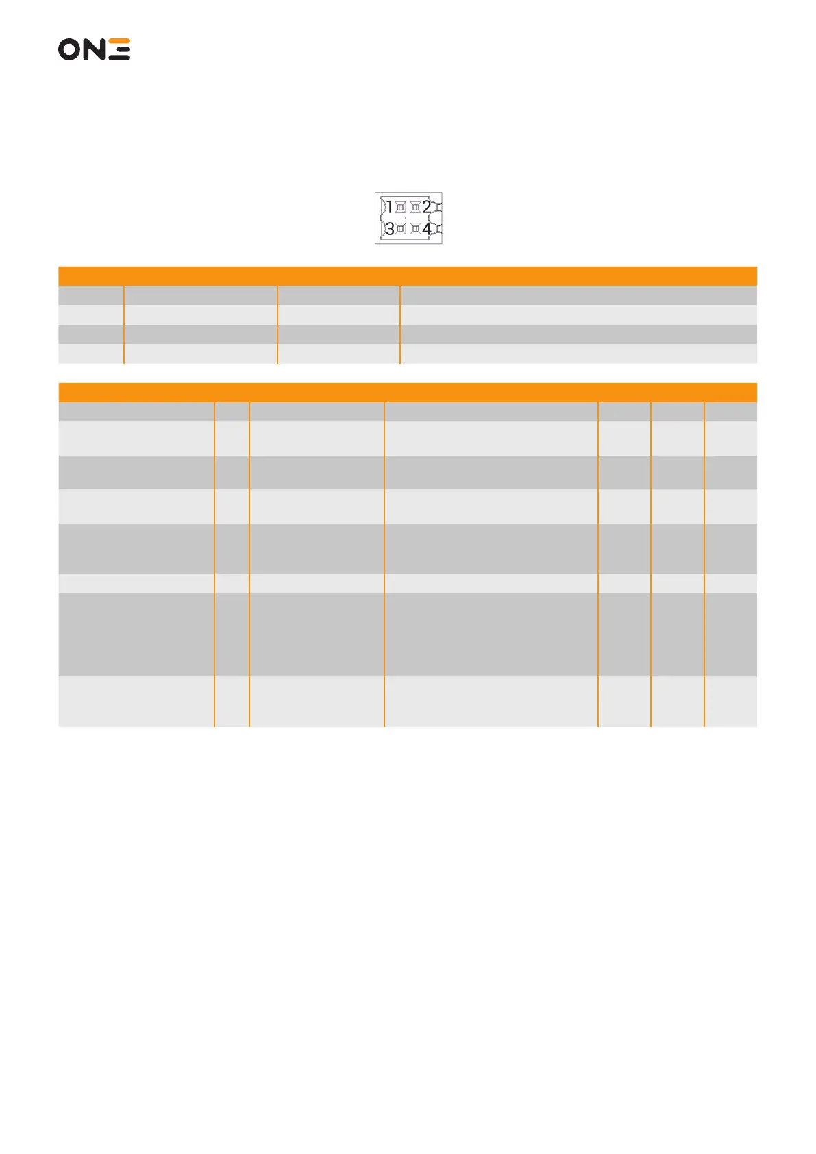
8.3.3 X5 Auxiliary I/O
Pin Signal Direction Description
1 DIGITAL_IN_P Input Source of auxiliary Digital Input
2 DIGITAL_IN_N Input Sink of auxiliary Digital Input
3 DIGITAL_OUT Output Pairing Lamp command
4 DIAG_OUT Output Diagnostic Output of safety logic
Parameter Pin Power Supply Limits Conditon Min. Typ. Max
Differential Input Voltage 1 - 2 Absolute maximum - -35 V - 35 V
Current absorbed by
auxiliary Input
1 - 2 Operating
Over operating temperature range
and voltage ranges
-20 mA - 20 mA
Input voltage sensed as
“Auxiliary input is OFF”
1 - 2 Operating - -32 V - 5V
Input voltage sensed as
“Auxiliary input is ON”
1 - 2 Operating - 15 V - 32 V
Voltage on the Output
in the high impedance
state
4 Operating - 0 V - 32 V
DIAG_OUT current 4 Operating - 0 A - 0,5 A
Voltage drop between
DIGITAL_OUT and the
supply ground connect-
ed to Pins 1-2 (in the low
impedance state)
3 Operating
At 0,5 A, over operating tempera-
ture range and voltage
- - 0,5 V
Leakage current of the
auxiliary output (in the
high impedance state)
3 Operating
Over operating temperature, volt-
age and current ranges
- - 10 µA