MANUGENX5 - Version 1.01 24.03.2021
© 2021 0N3 s.r.l. - Subject to change without notice
51
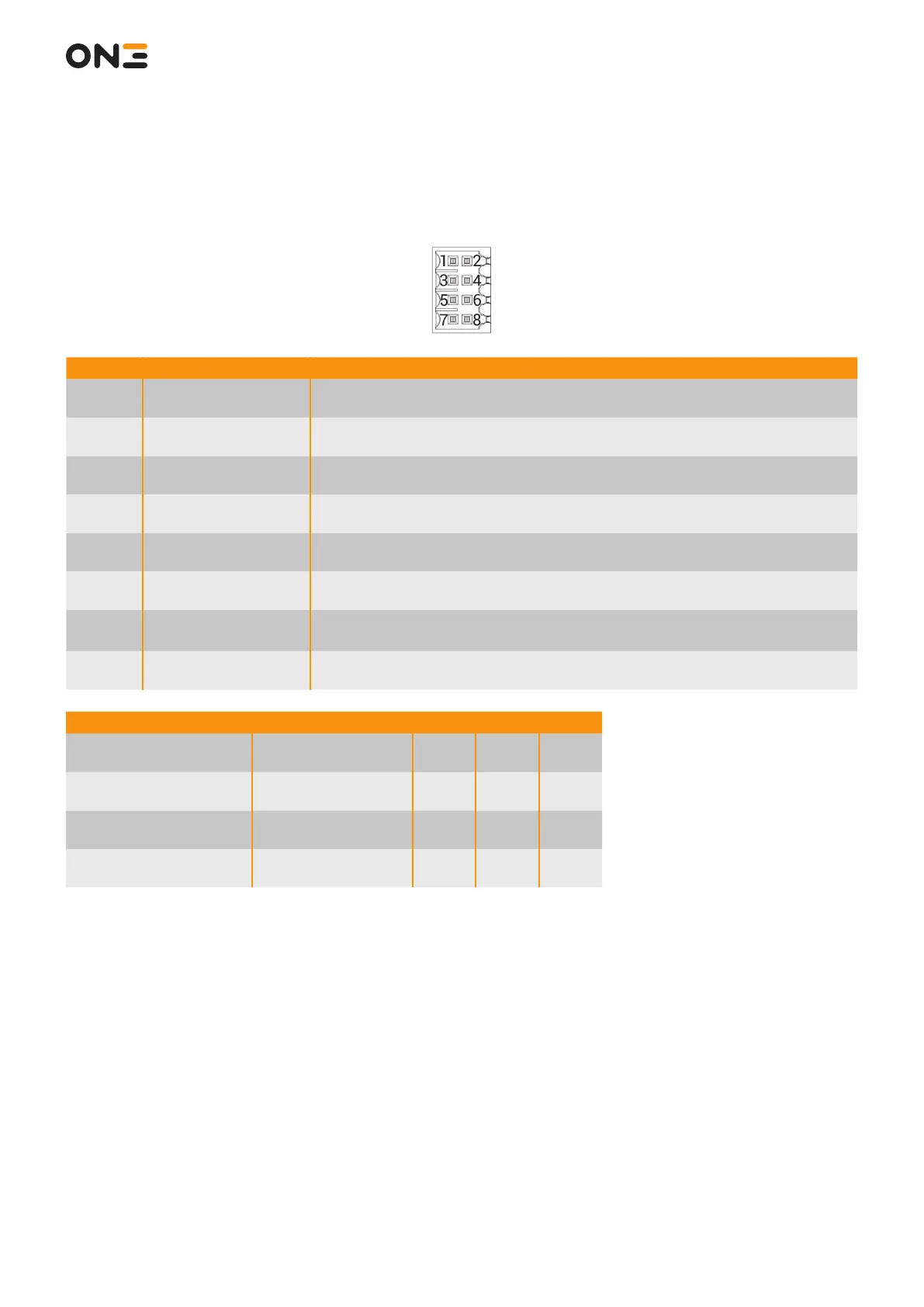
8.3.4 X6 Safety Outputs
The connector provides the contacts for Emergency Stop and Enabling Button contacts.
Pin Signal Description
1 RELAY_A1
Safety contact “A1”.
Emergency Stop Button contact #1
2 RELAY_A2
Safety contact “A2”.
Emergency Stop Button contact #1
3 RELAY_B1
Safety contact “B1”.
Emergency Stop Button contact #2
4 RELAY_B2
Safety contact “B2”.
Emergency Stop Button contact #2
5 RELAY_C1
Safety contact “C1”.
Enabling Button contact #1
6 RELAY_C2
Safety contact “C2”.
Enabling Button contact #1
7 RELAY_D1
Safety contact “D1”.
Enabling Button contact #2
8 RELAY_D2
Safety contact “D2”.
Enabling Button contact #2
Parameter Power Supply Limits Min. Typ. Max
Voltage across
the safety output
Absolute maximum -35 V - 35 V
Current through
the safety output
Absolute maximum -0,7 A - -0,7 A
Voltage across
the safety output
Operating - 32 V - 32 V
Current through
the safety output
Operating - 0,5 A - 0,5 A