MANUGENX5 - Version 1.01 24.03.2021
© 2021 0N3 s.r.l. - Subject to change without notice
52
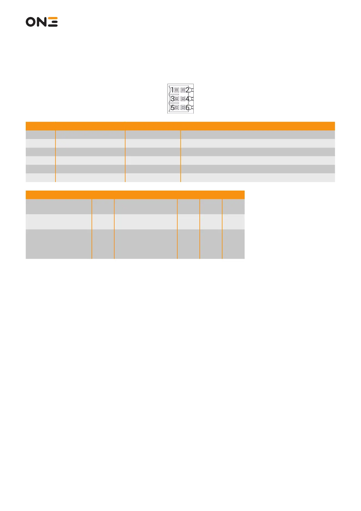
8.3.5 X7 Selector Outputs
Pin Signal Direction Description
1 +VBB - Source of Solid State Outputs
2 GND_BB - Sink of Solid State Outputs
3 SS_OUT_B0 Output Selector OUT – B0
4 SS_OUT_B1 Output Selector OUT – B1
5 SS_OUT_B2 Output Selector OUT – B2
6 SS_OUT_B3 Output Selector OUT – B3
Parameter Pin Power Supply Limits Min. Typ. Max
Supply voltage applied
for contact
1 - 2 Absolute maximum -35 V - 35 V
Supply voltage applied
for contact
3 - 4
5 - 6
Operating 10 V 24 V 32 V
Current coming out
from safety output (in
the low impedance
state)
3 - 4
5 - 6
Operating 0 - 0,5 A