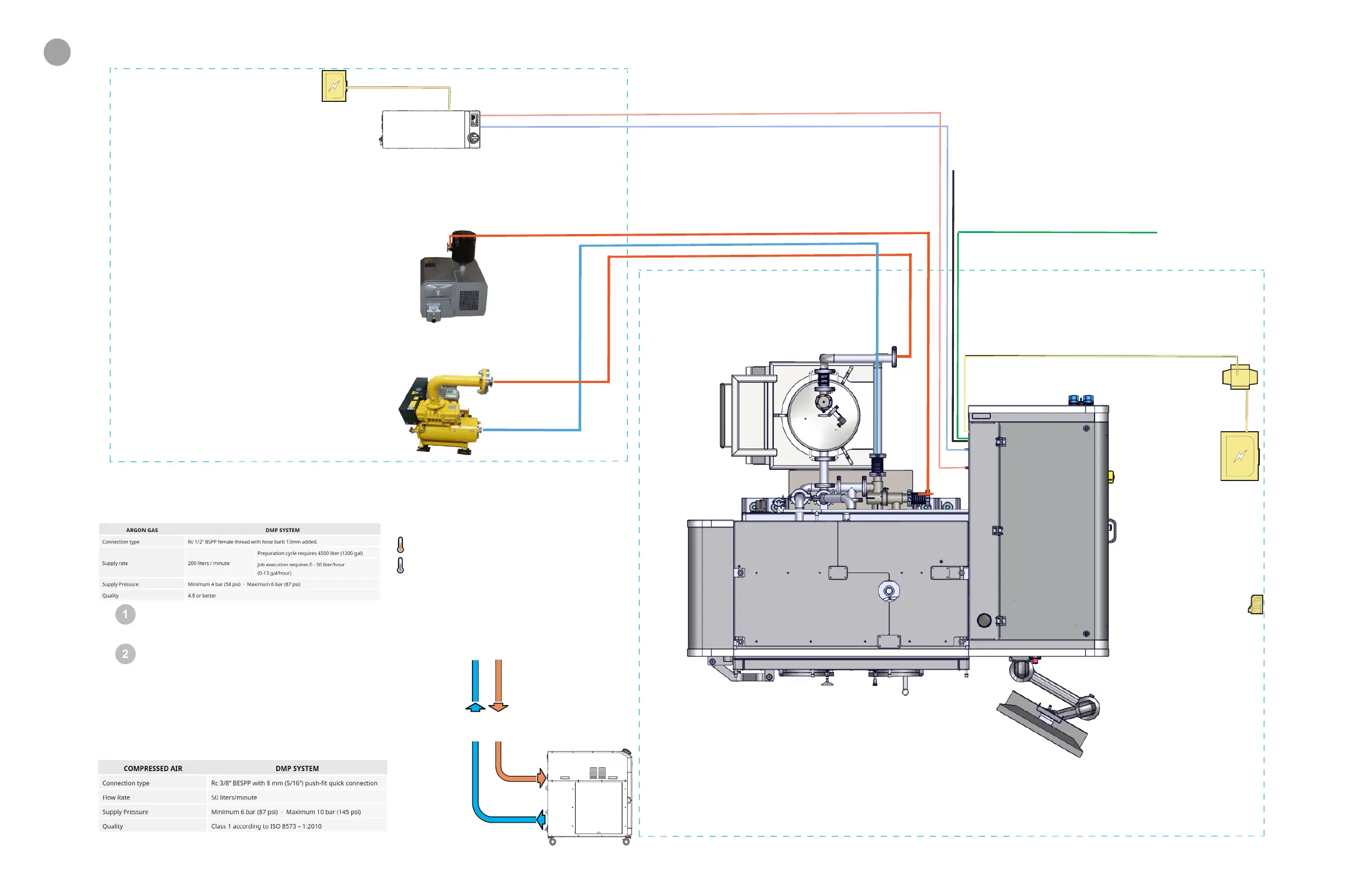
Control Cabinet
power panel
• 400 VAC
• 50/60 Hz
• 10 kVA
Build Room
Technical Room
Chiller power
• Separate from
DMP Flex 350
• 200 to 230 VAC
• 50/60 Hz
• 15 Amp
• C
ustomer supplied/installed
Additional argon gas line
• Customer supplied
Additional compressed air line
• Customer supplied
Additional signal cabling
• Customer supplied
Additional power cabling
• Customer supplied
Additional piping for vacuum pump and blower
• Customer supplied
• Maximum length is 10 meters
• Pipe must be stainless steel (303 or 304 is recommended)
• Customer must supply welding personnel
Transformer
(optional)
Room oxygen monitor
• Recommended
• Customer supplied/installed
Argon
• Customer supplied/installed
Compressed Air
• Customer supplied
/installed
Electrical Cable
• Customer supplied
/installed
Argon Gas
Bulk Argon tank
▪ Option for high argon demand sites
Argon cylinders
▪ Use a high volume pressure reducer
▪ Connect cylinders with auto-switching
manifold to ensure constant argon
supply during build
Compressed Air
min
16° C (60° F)
27° C (80° F)
max
Room temperature
setpoint and stability
• Set temperature between 18° C and 24° C (65° F and 75° F)
• Temperature should be constant to ±2° C (± 5° F)
Atmosphere
Coolant Hoses
▪ Included with 3D Systems-supplied chiller
▪ 1/2" barbed hose fitting
FACILITY REQUIREMENTS POSTER - SPLIT INSTALLATION