64171, Rev. 10/May 2019
3M™ GMI™ PS200 PORTABLE GAS MONITOR
OPERATION
3-6
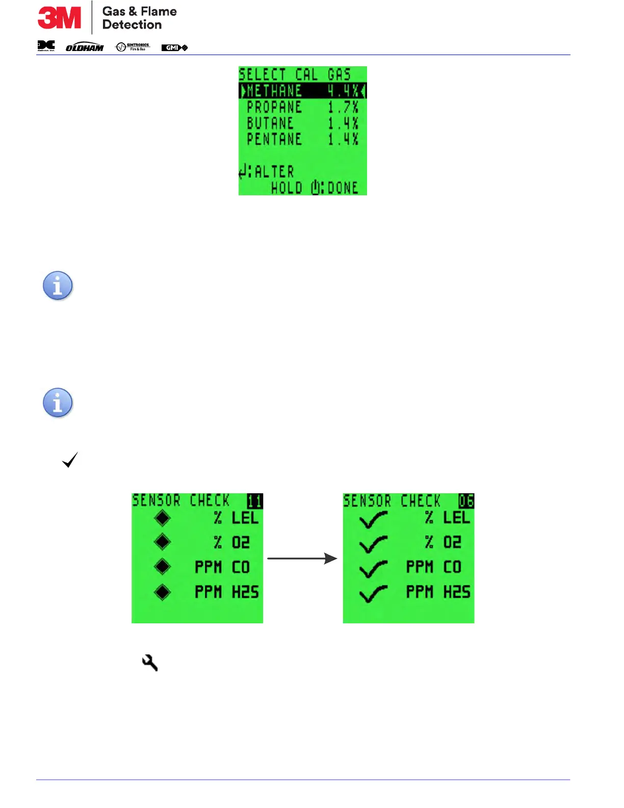
Figure 3-11: Cal Gas Selection
When this option is displayed (see
Figure 3-11: Cal Gas Selection), the original gas used to calibrate the
monitor is identified between two arrowheads.
To select a different gas:
1. Press the L button to step through the options.
2. Press and hold the R button to select the required option.
3.3.8. SENSOR CONFIRMATION CHECK
The symbol appears next to each sensor type to confirm that the sensor has been zeroed cor-
rectly, as shown in
Figure 3-12: Sensor Check Displays.
Figure 3-12: Sensor Check Displays
If a wrench symbol is displayed, refer to
Section 5.3. Zero Fault and Section 5.4. Sensor Faults.
3.3.9. NORMAL OPERATING DISPLAY
When warm-up is completed successfully, the backlight switches off and the normal operating
screen is displayed, as illustrated in
Figure 3-13: 4-Gas Normal Operating Display.
NOTE: The calibration certificate also identifies the calibration gas type used.
NOTE: Accuracy for the re-selected gas type is ± 20%.

 Loading...