page 11 | Document No.: TH-930-001 - 1/26/2015
A10 Thunder Series 930 Installation Guide
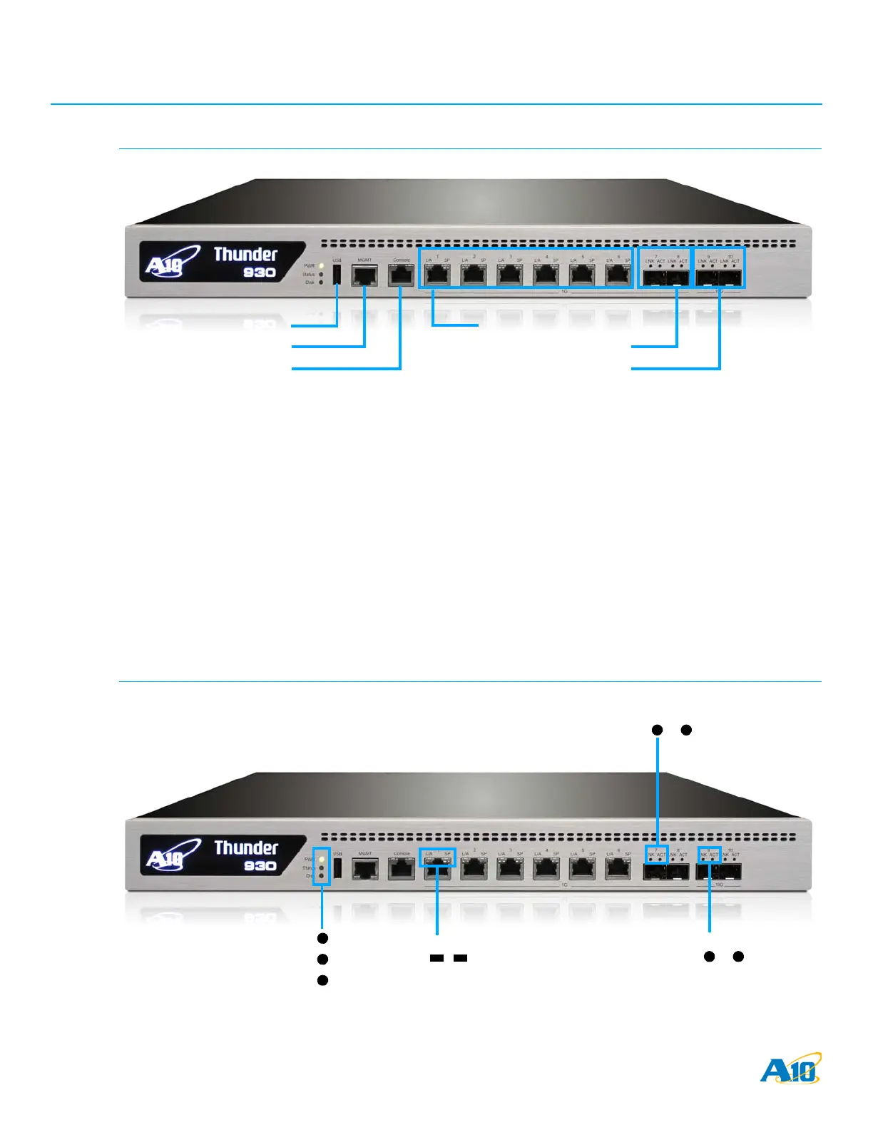
LED Locations and Status Indicators
FIGURE 2 Interface Locations and Numbers
To begin using these interface connections:
1. Connect the serial cable to the serial console interface.
2. Connect Ethernet cables to the data interfaces you plan to use.
3. Optionally, connect an Ethernet cable to the MGMT interface.
LED Locations and Status Indicators
The figures in this section provide close-up views of the interfaces and LEDs on your system.
FIGURE 3 LED Locations
#1 #2 #3 #4 #5 #6
#7 #8 #9 #10
USB
Management
Console
1 GB Copper Data Interfaces
1 GB Fiber Data Interfaces
10 GB Fiber Data Interfaces
PWR
STAT
DISK
LNK ACT
1 GB Fiber Interface LEDs
LNK ACT
10 GB Fiber
1 GB Copper
Interface LEDs
Interface LEDs
L/A SP
 Loading...