AMT/PTD/PBX/0020/2/4/EN 01/2007 Page 157
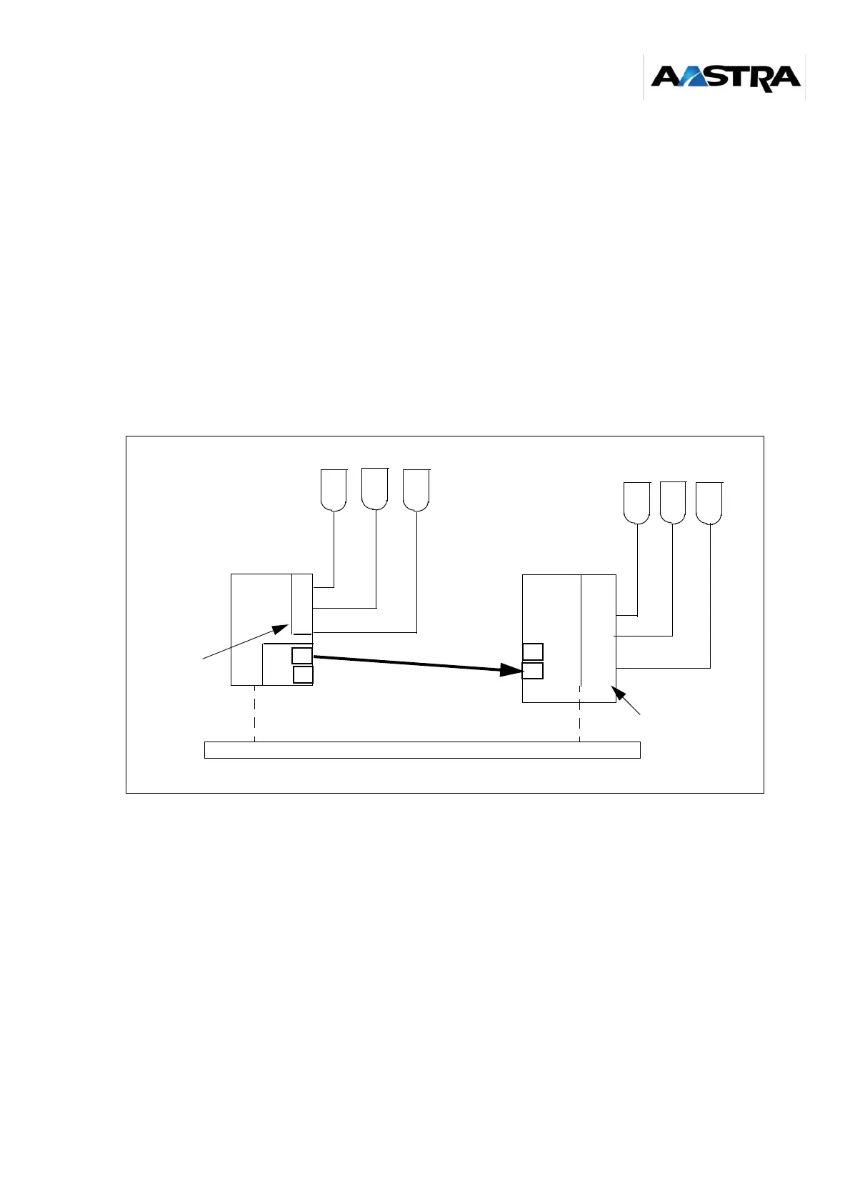
Case of multisite F4/F4, F4/F6 or F4/F1 device with F4 equipped with an
FPHBG2 back plane and CSI and LDT cards
The secondary port of the “Master” PBX is connected to the primary port of the “Slave” PBX.
The base stations must be wired in two pairs. The synchronization signal is carried by the M bit in
the S frame.
Note:
For a multisite F4/F6, if the DECT base stations are connected to the integrated S0
accesses of a NeXspan S CPU board, a third pair is required for synchronization.
Note: The LD4X mode (removing the J14 jumper on an LD4NX card and used to implement
additional functions) is only compatible on NeXspan S/L/D with software release R4.1
and above.
Figure 7-22: Contiguous multisite F4/F4, F4/F6 or F4/F1 (with F4 fitted with FPHBG2/CSI/LDT card)
F4
L
D
T
F4
or
F1
or
F6
L
D
4
IP or T2 network
S0 bus
S0 bus
master PBX
slave PBX
DECT base stations
L
D
T
/
L
D
4
N
X
BCSI
N
P
P
N
slave cards
slave card
DECT base stations