AMT/PTD/PBX/0020/2/4/EN 01/2007 Page 83
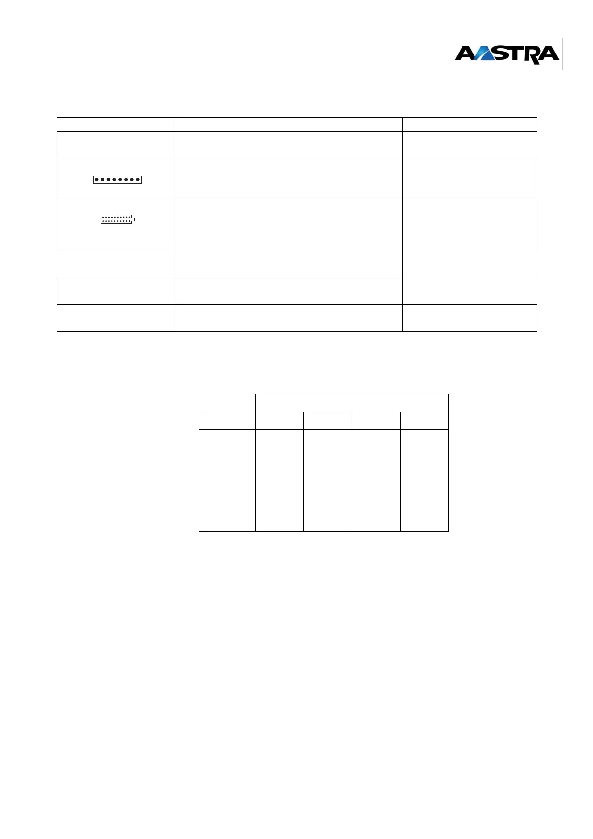
4.6.1 Description of the connectors
(1) See the details of the connections in Table 16:.
Table 15: Description of LD4NX RJ card connectors
• S0 connector pinout on the LD4NX RJ card: check that signals match pins.
Table 16: S0 connector pinout on the LD4NX RJ card
Caution: The ISDN 40V mains is supplied by the XL PBX backplane (provided the ADS300X
power supply unit with ISDN 40V is installed, ref: HR6953D).
LABEL FUNCTIONS/CHARACTERISTICS CONTACTS
J1 96-pin connector:
backplane connection.
J4 HE14 connector - 1 x 8 male pins: used for
loading programmable components "On Site"
(reserved for manufacturer).
not used
J5 and J6 Two connectors AMP CMS 2 x 10 female pins:
hosts an ADPCM16V daughter card.
Caution: the ADPCM8V daughter card is not
managed by the LD4NX RJ card.
console RJ45 -8 pin connectors: debug console, reserved
for manufacturer.
S0 to S3 RJ45 -8 pin connectors:
connection to S0 interface.
(1)
T0 to T3 RJ45 -8 pin connectors:
connection to T0 interface.
(1)
LINE NO.
Pin No. S3 S2: S1 S0
1
2
3
4
5
6
7
8
RD3
ED3
NED3
NRD3
RD2
ED2
NED2
NRD2
RD1
ED1
NED1
NRD1
RD0
ED0
NED0
NRD0