AMT/PTD/PBX/0020/2/4/EN 01/2007 Page 81
4.5.3 Description of the diodes
Table 13: Description of LD4NX ST card LEDs
4.5.4 Position of LD4NX ST card
The possible slots and restrictions for the LD4NX card in LD4N mode in a NeXspan cabinet are
the same for the LD4 card, see § 4.6.5.
Caution: The restrictions concerning installation of LD4 and LD4NX cards in LD4N
mode do not exist for LD4NX card in LD4X mode, see § 4.6.5 .
Note:
The LD4NX ST card can be hot-plugged/removed in an operational XL PBX or a
rackable XS PBX.
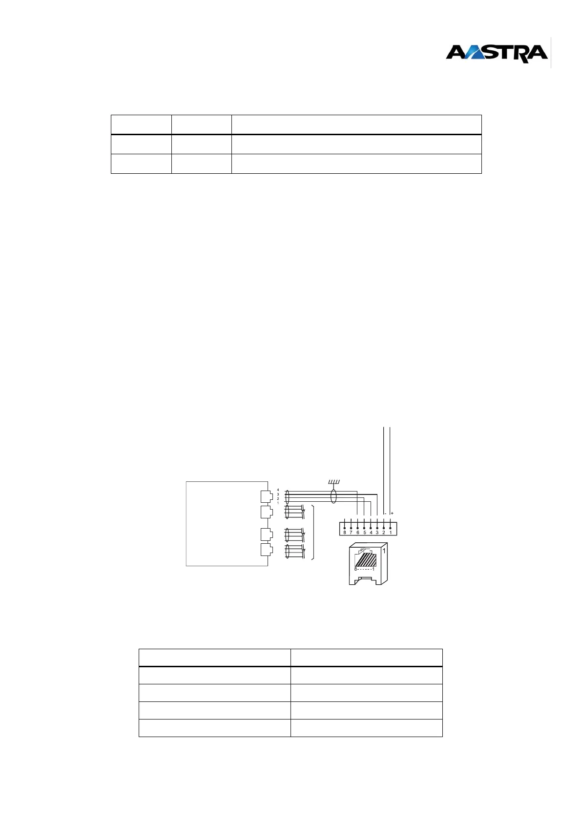
4.5.5 Connecting base stations
Each base station is connected to the ISDN S0 (BRI) of an LD4NX ST card, and uses two pairs:
1 transmit pair and 1 receive pair.
Note:
If there are a DECT base station and an S0 terminal (other than the base station) on the
same card, the base station must be powered with a 40 V supply.
Figure 4-8: Connecting a base station to an S0 interface of an LD4NX ST card
S0 interface link with DECT base station:
Table 14: S0 interface link of an LD4NX ST card with a DECT base station
Label Color Feature
RUN Green Shows the operating status of the card
DISABLED Orange Not used
4-pin STOCKO connector Base station RJ45 connector
Pin 4 (NRD0) Pin 6
Pin 3 (RD0) Pin 3
Pin 2 (NED0) Pin 5
Pin 1 (ED0) Pin 4
LD4N card
J7
J8
J9
J10
Identical
SYNCHRO
Radio
Base
Station