AMT/PTD/PBX/0020/2/4/EN 01/2007 Page 31
2.2.4 Configuration of the old M6241 DECT base station
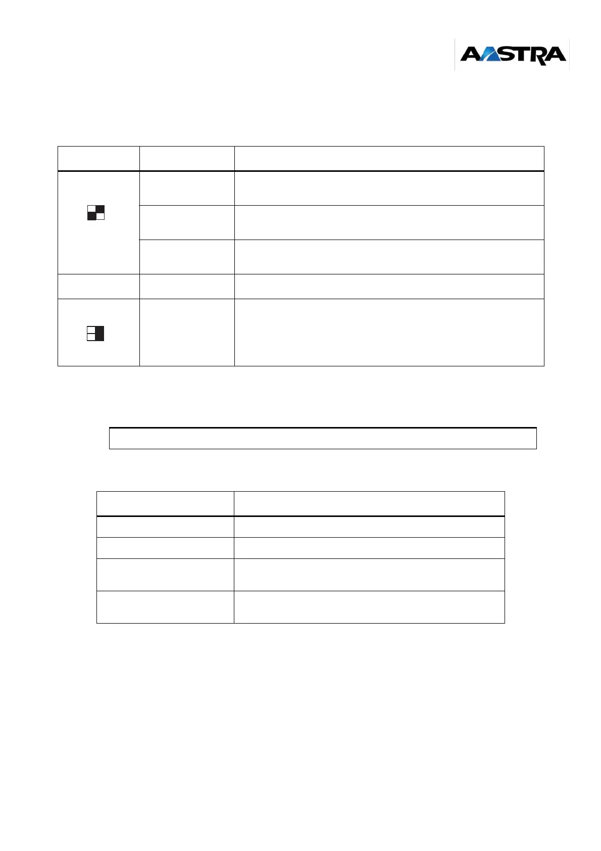
• Configuration of the switches on the base station’s electronic card (see figure 3 page 25):
The black square represents the position of the switch.
Table 5: Configuration of the electronic card switches of the old M6241 base station
• Base station status indicators:
Table 6: Working light-emitting diodes (LED) on the old M6241 base station
Switches CA1 Status Description
CA1-1 on ON
Activation of the adaptation resistor on the synchronization pair
(factory configuration)
CA1-2 on ON
The base station reset is only activated when the base station or
PBX power is on
CA1-2 on OFF
The base station reset is controlled by level 1 of the S0 interface
(factory configuration)
Switches S202 Status Description
S202-1 on ON
and S202-2 on ON
Activation of the adaptation resistors (100 ohms) on the S0 pairs.
CAUTION: do not change the factory delivery configuration of S202 and CA1
Status Explanation
Message lamp (off) The base station is not powered.
Illuminated steady The base station is powered but is not in service.
Slow flashing The base station is loaded. The link with the PBX is operational.
If DECT synchronization is active, the base station can be used.
Flashing rapidly The base station is active and the 4 channels are in
communication.
CA1
ON
2
1
S202
ON