AMT/PTD/PBX/0020/2/4/EN 01/2007 Page 73
Table 4: Description of switches SW7 and SW8 on the LD4 ST card
4.3.3 Position of LD4 ST card
The possible slots and restrictions for the LD4 card in a NeXspan cabinet are the same as for the
LD4NX card see § 4.6.5.
4.3.4 Connecting base stations
Each terminal is connected to the ISDN S0 (BRI) of an LD4 ST card, and uses two pairs: 1
transmit pair and 1 receive pair.
Note:
if there are a DECT base station and an S0 terminal (other than the base station) on the
same card, the base station must be powered with 40 V. The NeXspan power supply
units do not supply ISDN 40 V. To supply 40 V to sets and/or base stations, connect an
external power supply unit to the J2 connector on the LD4 ST card.
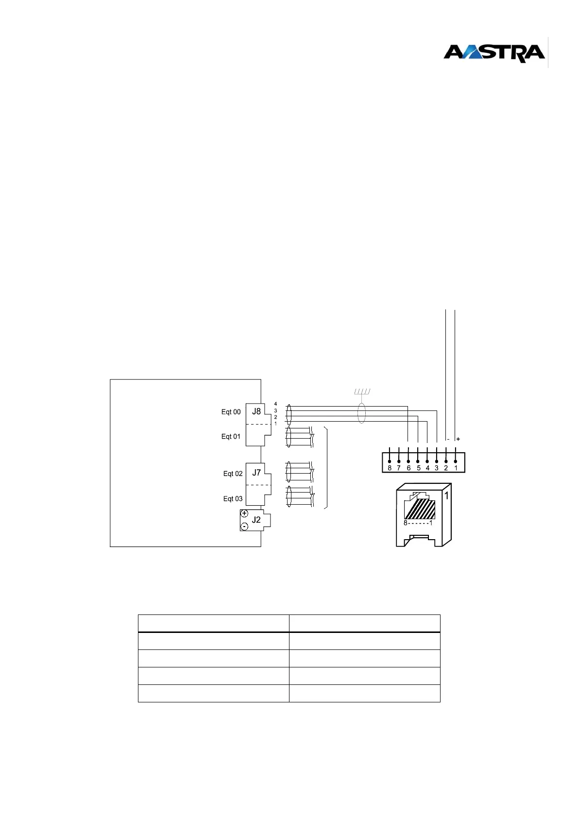
Figure 4-3: Connecting a base station to an S0 interface of an LD4 ST card
S0 interface link with DECT base station:
Table 5: S0 interface link of an LD4 ST card with a DECT base station
8-pin STOCKO connector RJ45 connector
Pin 4 (NRD1) Pin 6
Pin 3 (RD1) Pin 3
Pin 2 (NED1) Pin 5
Pin 1 (ED1) Pin 4
LD4 board
SYNCHRO
Identical
Radio
base
station