AMT/PTD/PBX/0020/2/4/EN 01/2007 Page 79
4.5.1 Description of the connectors
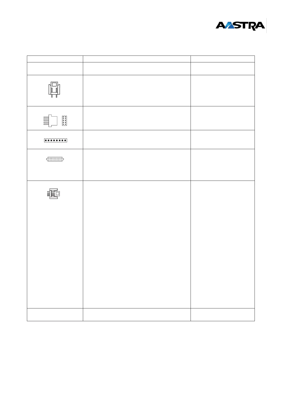
Table 11: Description of the LD4NX ST card connectors
LABEL FUNCTIONS/CHARACTERISTICS CONTACTS
J1 96-pin connector:
backplane connection.
J2 STOCKO male connector, 2 pins: receives the
ISDN 40 V remote power supply when the latter is
not available on the PBX backplane (40 V only
supplied on the backplane of a NeXspan-range
XL PBX) .
•Pin 1: M40V
• Pin 2: P40V
J3 HE14 connector - 2 x 5 male pins, (debug
console, reserved for manufacturer).
not used
J4 HE14 connector - 1 x 8 male pins: used for
loading programmable components "On Site"
(reserved for manufacturer).
not used
J5 and J6 Two connectors AMP CMS 2 x 10 female pins:
hosts an ADPCM16V daughter card.
Caution: The ADPCM8V daughter card is
not managed by the LD4NX ST
card.
J7 to J10 Four STOCKO male connectors, 4 pins:
connection of the S0/T0 interfaces.
Interface 0 (on J7):
•Pin 1: ED0
•Pin 2: NED0
•Pin 3: RD0
• Pin 4: NRD0
Interface 1 (on J8):
•Pin 1: ED1
•Pin 2: NED1
•Pin 3: RD1
• Pin 4: NRD1
Interface 2 (on J9):
•Pin 5: ED2
•Pin 6: NED2
•Pin 7: RD2
• Pin 8: NRD2
Interface 3 (on J10):
•Pin 1: ED3
•Pin 2: NED3
•Pin 3: RD3
• Pin 4: NRD3
J11 Male connector, 3 pins, (CPUTIME tool, reserved
for manufacturer).
not used
2
1
A B
A B
1
2
3
5
4
1
2
3
5
4
1