Page 94 01/2007 AMT/PTD/PBX/0020/2/4/EN
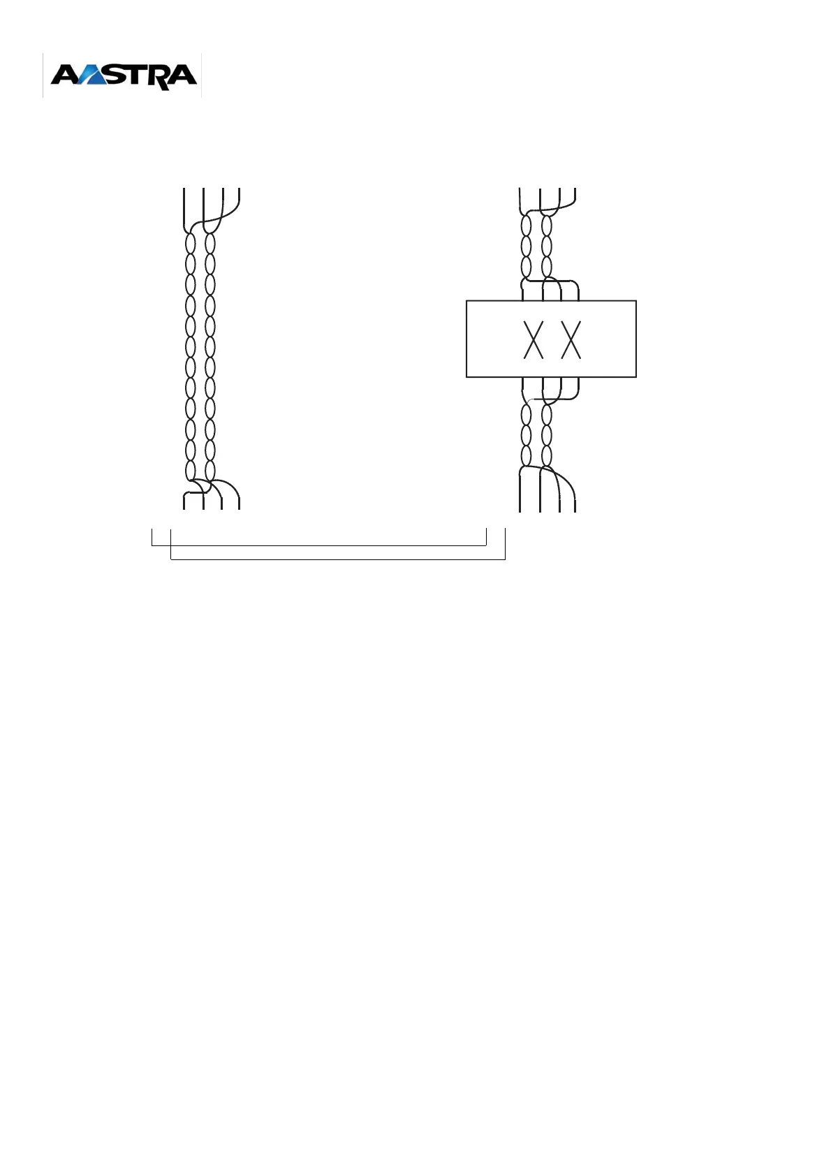
Figure 4-21: Connecting two DECT base stations to an S0 access of an LD4/LD4NX card and a UCT1-S/
UCT1S-12/UCT1-C card
In certain special cases (multi-site network with PBXs of different types, for example, or a multi-
site network with several XSs whose base stations are connected to integrated S0 accesses of
UCT1-S cards), a third pair may need to be wired for synchronization (pins 1 and 2 of the base
station RJ45 connector); see the Chapter "Multi-site synchronization".
Note:
Multi-site DECT synchronization via third pair is not possible with NeXspan C and
NeXspan S12.
In a multi-site network with several NeXspan cabinets (XL/XS), synchronization is carried out
from one or two PBXs declared "Master".
UCT-L (XL processor card) and UCT-S cards (XS processor card) have two RJ45 connectors for
DECT synchronization: a primary port (J7A) and a secondary port (J7B) (see the Chapter "Multi-
site synchronization").
BX_MATRIX_XS_UCTS_CONNEXION_DECT_01_
01
DECT base
station
1234567
8
1234567
8
1234567
8
1234567
8
1234567
8
1234567
8
Twisted cable
Standard point-point cable
Crossover
box
Standard point-point cable
UCT1-S/UCT1-C
RJ45
LD4