26 266CRH / 266CRT, 266CSH / 266CST MULTIVARIABLE PRESSURE TRANSMITTER | OI/266CXX/MODBUS-EN REV. A
… 6 Installation
… Adjusting the transmitter position
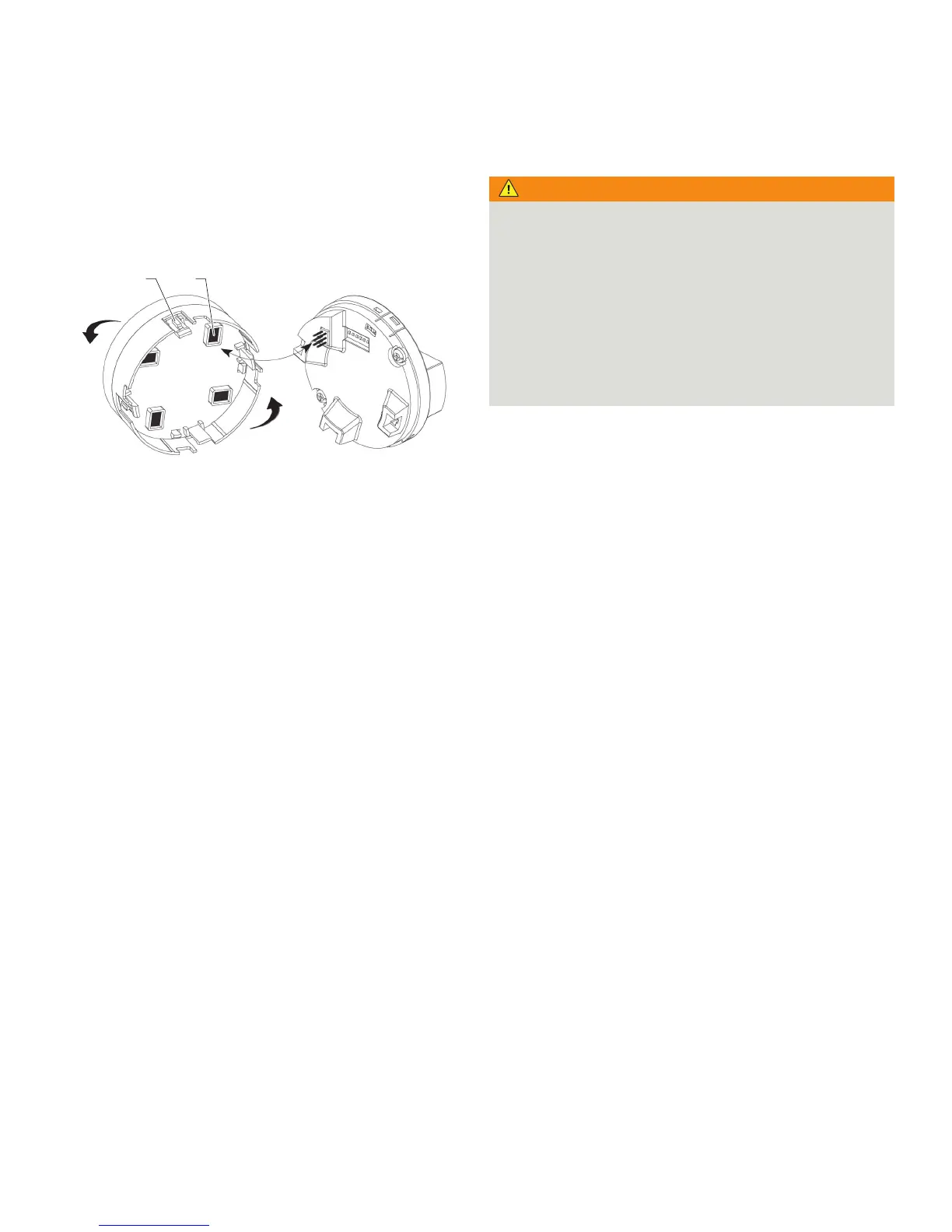
Rotate the LCD display
If the device has an integral LCD display, this can be mounted in
four different positions, each of which can be rotated
through 90°.
M10760-01
1 2
1 Fixing locks
2 Display connector
Figure 16: Rotating the LCD display
To rotate the LCD display, perform the following steps:
1.2pen the windowed cover (ensuring compliance with
special requirements for hazardous areas), Refer to
Opening and closing the housing on page 25.
2. Pull the LCD display out of the electronics module.
3. Reposition the LCD display connector accordingly.
4. Plug the LCD display back into the electronics module,
checking that the 4 plastic fixing locks are securely in
place.
5. Close the windowed cover.
Connecting impulse lines
WARNING
Bodily injury!
Leaks in the process lines can result in death or severe
injuries.
• Install and seal process connections and all accessory
elements (including valve blocks) before the charging the
device with pressure.
• For applications with toxic or hazardous substances prior
to venting or draining, take all precautionary measures
that are recommended in the respective safety data sheet.
• Only tighten the screws of the fastening accessories with
a size 12 mm (¹?32 in) hexagon socket wrench.
In order for the impulse lines to be laid correctly, the following
points must be observed:
• The impulse lines must be as short as possible and have
no sharp bends
• Lay the impulse lines so that no deposits can accumulate
in them. Gradients should not be less than approx. 8 %
(ascending or descending)
• The impulse lines should be blown through with
compressed air or, better still, flushed through with the
medium prior to connection
• With wet legs, the liquid in both lines must be at the same
level
• With vaporous measuring media, measures must be
taken to prevent steam entering the measuring chambers
of the measuring cell and causing overheating
• It may be necessary to use condensate vessels or similar
with small measuring spans and vaporous media
• If you are using condensate vessels (steam
measurement), you should ensure that the vessels are at
the same elevation in the differential pressure piping
• As far as possible, keep both impulse lines at the same
temperature
• Completely depressurize the impulse lines if the medium
is a liquid
• Lay the impulse lines so that gas bubbles (when
measuring liquids) or condensate (when measuring
gases) can flow back into the process line
• Ensure that the impulse lines are connected correctly
(connection of high-pressure and low-pressure sides to
the measuring cell, gaskets, etc.)
• All connections must be secure and tight
• Lay the impulse lines so that the medium cannot be
blown out over the measuring cell
For more details please read the operating instruction section
Mounting.