266CRH / 266CRT, 266CSH / 266CST MULTIVARIABLE PRESSURE TRANSMITTER | OI/266CXX/MODBUS-EN REV. A 35
Connection on the device
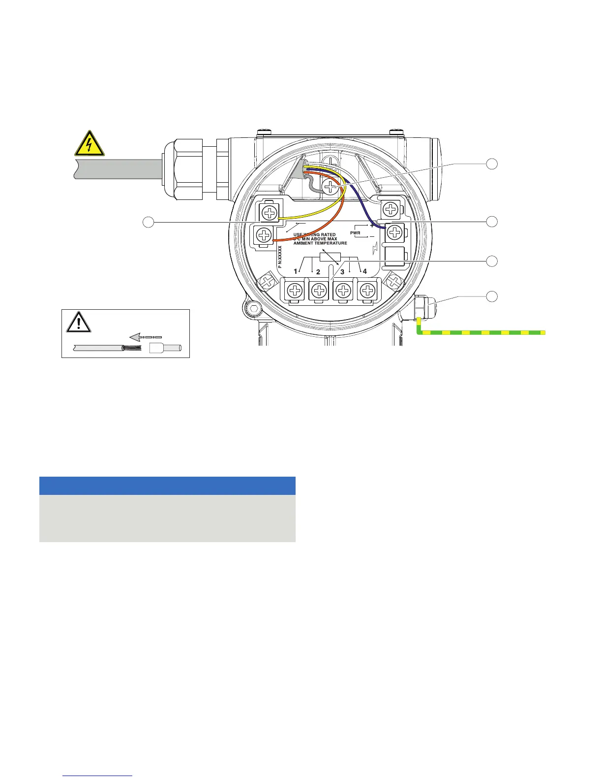
M11189
COMM.
A(+)
B(-)
SURGE
INSIDE
RTD
Modbus
9...30 V DC
PE
1
3
4
2
5
1 Terminals for Modbus® interface
2 Terminal for PE / Cable Shield
3 Terminals for power supply
4 Terminals for Pt100 resistance thermometer
5 Ground terminal
PE Potential equalization
Figure 29: Connection on the device (example)
Change from one to tw o columns
NOTICE
If the O-ring gasket is seated incorrectly or damaged, this
may have an adverse effect on the housing protection class.
Follow the instructions in Opening and closing the housing
on page 25 to open and close the housing safely.
Note
• Observe the power supply limit values in accordance with the
information on the name plate.
• Observe the voltage drop for large cable lengths and small
conductor cross-sections. The voltage at the terminals of the
device may not fall below the minimum value required in
accordance with the information on the name plate.
The power supply is connected to terminal PWR + and PWR Æ, as
stated on the name plate.
To connect the pressure transmitter, observe the following
instructions:
• Lead the cable for the power supply and the Modbus
connection into the terminal box.
• Lead the temperature sensor cable (if there is one)
through the second cable entry and connect it to the
designated terminals.
• Connect the cables in accordance with the electrical
connection diagram. Connect the cable shields to the
designated ground terminal in the terminal box.
• Connect the potential equalization (PE) on the ground
terminal to the terminal box.
• Use wire end ferrules when connecting.