266CRH / 266CRT, 266CSH / 266CST MULTIVARIABLE PRESSURE TRANSMITTER | OI/266CXX/MODBUS-EN REV. A 83
Mounting / dismounting the operating
button unit
M10804-01
1
2
3
4
5
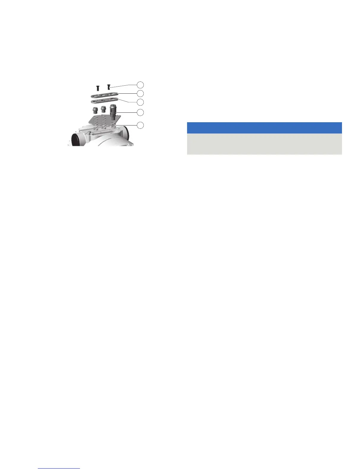
Figure 4: Operating button unit
1. Unscrew the fastening screws of the name plate and swing
the name plate to the side to obtain access to the local
operating elements.
2. Unscrew the fastening screws
1 of the button unit that hold
the spring-loaded plastic part.
3. Remove the seal
3 that is located below the plastic cover of
the button unit.
4. Now the three operating buttons
4 and the springs 5 can
be taken out.
Mounting / dismounting the LCD display
Refer to Opening and closing the housing on page 25 and
Rotate the LCD display on page 26.
1. On the side of the electronics module / LCD display, unscrew
the housing cover.
2. Fit on the LCD display. Depending on the install position of
the multivariable transmitter, the LCD display can be fit on in
four different positions. Consequently it can be rotated by
± 90° or ± 180°.
3. Screw on the housing cover hand tight.
Removing / installing the process flange
1. Unscrew the fastening screws of the process flanges in cross
pattern (hexagon socket wrench AF 13 mm (0.51 in).
2. Carefully take off the process flanges so that the separating
diaphragms are not damaged.
3. Clean the separating diaphragms, and if necessary the
process flanges with a soft brush and a suitable cleaning
agent.
NOTICE
Potential damage to parts!
Components can be damaged using the wrong cleaning tools.
• Do not use any sharp-edged or pointed tools.
4. Insert new O-rings into the process flanges.
5. Fit the process flanges onto the measuring cell.
The flange surfaces of both process flanges must be
positioned in one plane and at right angles to the electronics
housing (vertical process flanges are the exception).
6. Check the thread of the screws for the process flanges for
ease of movement. To do this, screw on the nuts by hand to
the screw head. If this is not possible, use new screws and
nuts.
7. Lubricate the screw thread and the seat of the threaded
union, for example with ‘Anti-Seize AS 040 P’ (supplier:
WEICON GmbH & Co.KG, Münster, Germany).
Note
For the oil-free and grease-free version, after installation of the
process flange, the measuring chambers must be cleaned again.
8. Installation of the process flanges:
• First tighten the screws / nuts of the process flanges
with a torque wrench to a pre-tightening torque of MJ = 2
Nm (0.2 kpm), working in a cross pattern.
• Then tighten the screws / nuts of the process flanges
with a pre-tightening torque of MJ = 10 Nm (1.0 kpm),
working in a cross pattern.
• Retighten all screws / nuts (in a cross pattern), this time
with a total tightening angle of ήA = 180°; in two steps,
90° for each step.
Some transmitters have size M10 screws. Tighten these
screws with a total tightening angle of ήA = 270°; in three
steps, 90° each step.