266CRH / 266CRT, 266CSH / 266CST MULTIVARIABLE PRESSURE TRANSMITTER | OI/266CXX/MODBUS-EN REV. A 39
… 7 Commissioning
Parameterization of the device
The transmitter is delivered preconfigured according to the
information provided when placing the order.
However, should a change to the configuration be necessary
(because measuring point data has changed since the original
plans were drawn up, for example), the following options are
available:
• Menu-led configuration of the transmitter with the
integral LCD display
• Configuration using a PC / Laptop with graphical user
interface (DTM). How to use these tools to make the
configuration settings is described in the corresponding
related documentation.
Factory settings
The transmitters calibrated in the factory to the measuring
range specified by the customer. The calibrated measuring
range and the measuring point tag are specified on an additional
labeling plate.
If nothing is specified by the customer in this regard, the
transmitter will be delivered with a standard configuration, that
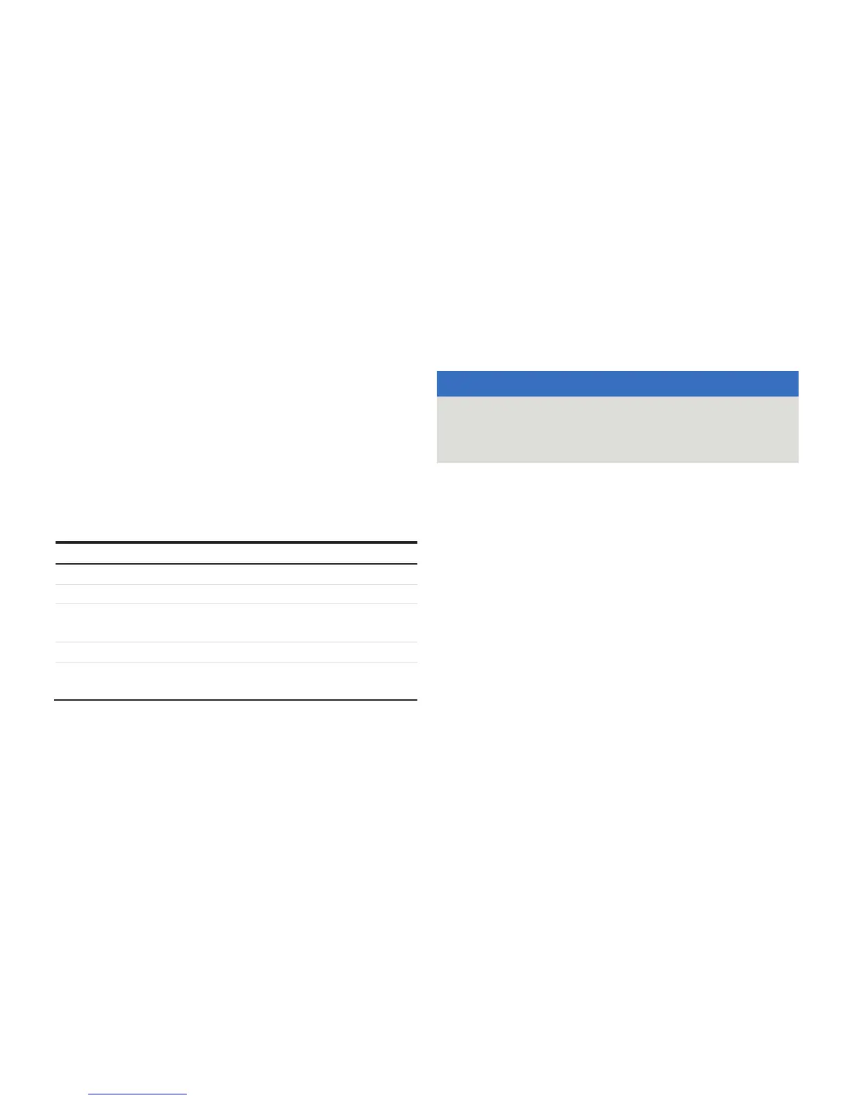
contains the following parameters (among others).
Parameter Factory setting
Measuring range start (LRV) Zero
Measuring range end (URV) Upper measuring range limit (URL)
Transmission function for the output Mass flow
Damping 1 second
Presentation of the optional LCD
display
Process value PV (1-place) and bar
diagram of the output signal
Each of the parameters listed here can be easily set via the
optional LCD display with operating menu, or the Device Type
Manager (DTM).
Configuration without integrated LCD
display
Note
The configuration possibilities described below are only possible
for the models 266Cxx with flow calculation or without
calculation function.
The correction of the mounting position and reset of bias are set
directly on the transmitter via the operating buttons. These
operating buttons are arranged under the rating plate.
In order to operate the device locally, unscrew the fixing screws
of the rating plate, and swing the name plate clockwise to the
side.
NOTICE
Material damage due to a magnetic field!
The use of magnetic screwdrivers results in damage of
components.
• Do not use a magnetic screwdriver to operate the buttons.
The transmitter has been calibrated by the manufacturer based
on the order information. The set measuring range start and
measuring range end are specified on the name plate.
For the connection, ensure that liquid residues (for gaseous test
materials) or air bubbles (for liquid test materials) are not in the
impulse line; because that can cause measurement errors in the
test.
It is recommended to set the damping to the value ‘zero’.
For correction of mounting position and static pressure
influence see .
A reset to factory setting of differential pressure can be done
with operating button ‘S’.