266CRH / 266CRT, 266CSH / 266CST MULTIVARIABLE PRESSURE TRANSMITTER | OI/266CXX/MODBUS-EN REV. A 37
Setting precalibrated devices
Note
266Cxx transmitters do not support this function if the ‘Level
measurement’ calculation function has been activated. In this
case, the correction must be made using the optional LCD
indicator or the DTM.
• For this purpose, the DIP switch on the electronics board
must be set to position ‘0’, see DIP switches on the
secondary electronics on page 38.
A PV Bias / Offset correction can be performed via the local push
buttons as follows:
1. Separate the transmitter from the process and equalize
the pressure in the two measuring chambers by adjusting
the bypass valve in the manifold.
2. Check the transmitter output signal:
• If it is PV = 0, zero point correction is not required.
• If the output is not at zero, proceed as follows:
3. Unscrew the screws attaching the name plate to the top
of the transmitter housing.
4. Rotate the name plate so that the push buttons can be
accessed.
5. Check that the write protection rotary switch is set to
write enable.
6. Press and hold down the zero button (Z) on the top of the
transmitter for at least 3 seconds.
• The output signal switches to PV = 0 and the message
‘OPER DONE’ appears on the LCD display (if there is one).
• If nothing happens, check the write protection rotary
switch.
It is probably set to write protection. For all other
diagnosis notices, refer to the instructions.
7. As soon as zero point correction is complete, reconnect
the transmitter to the process.
8. Open the pressure equalization valve on the manifold.
9. Open the shut-off valve of high-pressure side.
10.Open the pressure equalization valve on the manifold.
11. Open the shut-off valve on the low-pressure side.
Hardware settings
Write protection switch
M10761-01
A
B
1
2
3
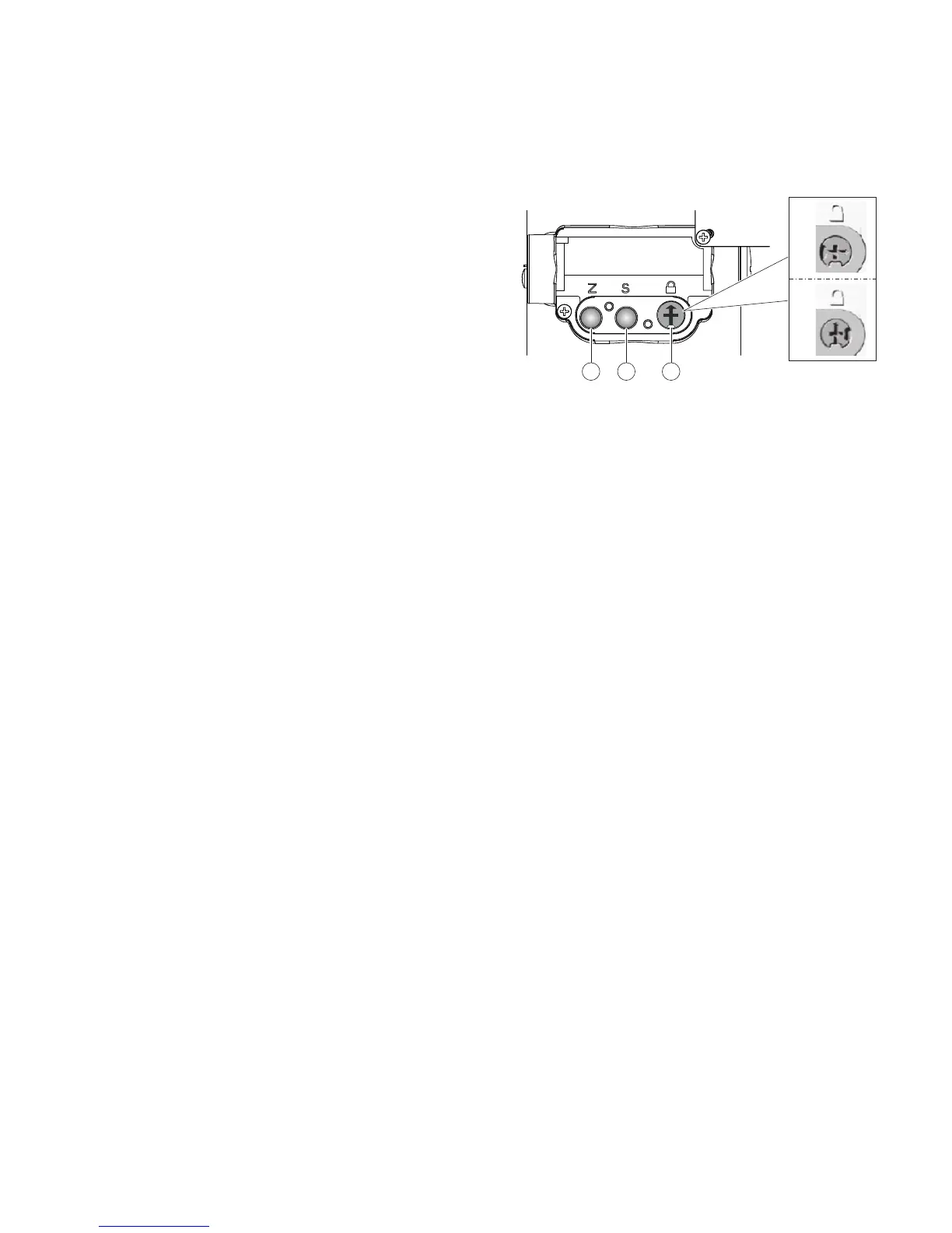
1 Zero
2 Span
3 Write protection switch
Figure 31: Operating buttons, write protection turn switch
The write protection prevents unauthorized users from
overwriting the configuration data.
• With activated write protection the operating buttons
‘0% (Z)’ and ‘100 % (S)’ have no function.
• A change of parameters with the integral LCD indicator, via a
handheld terminal, or the user interface (DTM) are not
possible either.
However, the configuration data can be read out via the graphic
user interface (DTM) or a comparable communication tool. If
needed the operating device can also be sealed with a lead seal.
Write protection can be activated as follows (see also the
symbols on the plate).
1. Remove the nameplate by releasing the holding screw lying
on the bottom left corner
2. Use a suitable screwdriver to press the switch all the way
down.
3. Turn the switch 90° clockwise.
Note
To deactivate write protection, press the switch down slightly
and then turn it counterclockwise 90°.
Note
The product has an ABB service account that can be disabled
with this write protection switch.