266CRH / 266CRT, 266CSH / 266CST MULTIVARIABLE PRESSURE TRANSMITTER | OI/266CXX/MODBUS-EN REV. A 27
Process connections
M10801-01
1 2 3
4
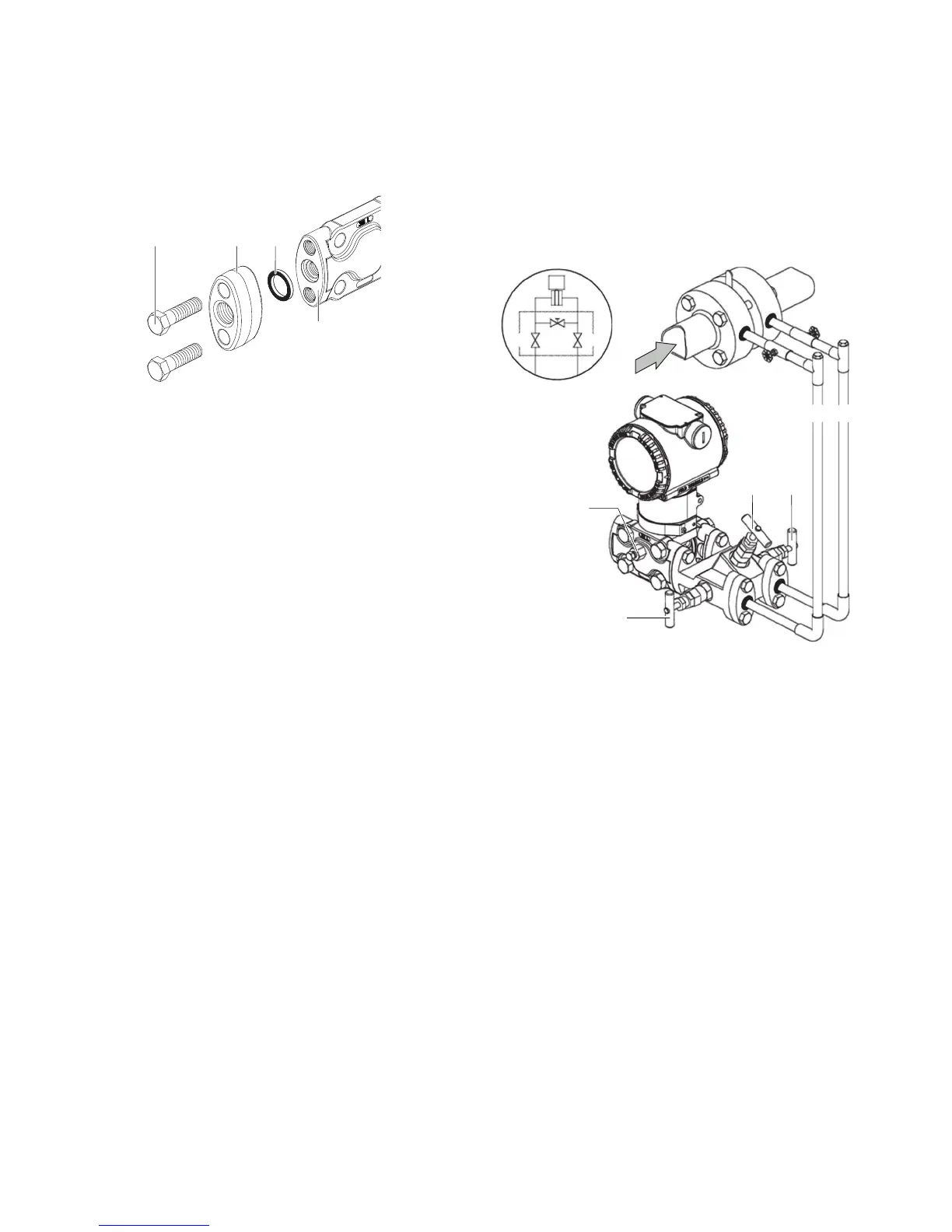
1 Screws
2 Flange adapter
3 O-ring
4 Transmitter connection flange
Figure 17: Process connection
On the flange of the 266 multivariable transmitter there are
¼ to 18 NPT process connections with middle point spacings of
54 mm (2.13 in). The process connections on the flange enable
direct attachment of 3 elements or 5 element valve manifolds.
Optionally flange adapters with ½ to 14 NPT connections are
available. By turning one or both adapters, middle point spacing
of 51 mm (2.01 in), 54 mm (2.13 in) or 57 mm (2.24 in) is possible.
Mount the adapters as follows:
1. Correctly position the adapters with inserted O-ring.
2. Screw the adapters on the transmitter connection flange
with the provided screws.
Tighten the screws as follows: Preliminary tightening
hand tight, preliminary tightening with 10 Nm, final
tightening with 50 Nm.
Mounting recommendations
The arrangement of the impulse lines depends on the respective
measurement application.
Flow measurement of steam (condensible vapor) or clean
liquids
M10763-01
4
1
3 2
H L
H L
1 2
3
H High pressure side
L Low pressure side
1 High-pressure valve
2 Low pressure valve
3 Equalizing valve
4 Vent / Drain valve
Figure 18: Steam flow measurement
• Place taps to the side of the process line.
• For liquid measurements, mount the transmitter next to or
underneath the taps, for steam measurements underneath
the taps.
• Mount the vent / drain valve pointing upward.
• For steam applications, fill the vertical section of the impulse
lines with a compatible fluid through the appropriate filling
connections.
The height of the liquid column between process line and
transmitter must be the same on the high pressure side and the
low pressure side, so that an accurate measurement is ensured.
For implementation of this requirement it can be practical for
steam measurements, to use the impulse lines condensate
tanks.