1 2
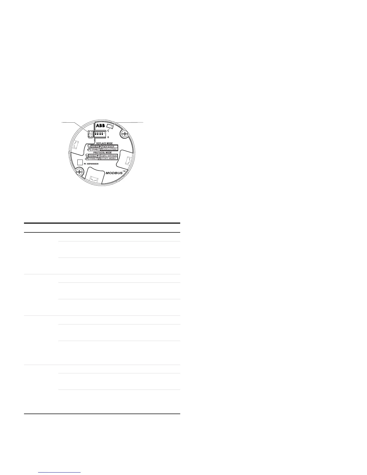
1 Interface for LCD indicator and service port
2 DIP switches
Figure 32: Communication board Modbus
DIP switch Function
SW 1.1
REPLACE MODE (transfer system data)
On (1): Enable:
Replacement mode active
Off (0): Disable:
Replacement mode deactivated
SW 1.2
REPLACE MODE (data transfer direction)
On (1): New sensor:
When replacing sensor
Off (0): New electronic:
When replacing secondary electronics
SW 1.3
PROTOCOL MODE
On (1): Enable:
Selection of communication protocol via SW 1.4
Off (0): Disable:
Selection of communication protocol via LCD
display, DTM or Modbus
SW 1.4
PROTOCOL MODE
On (1): Configure/HART-RS485:
Parameterization via DTM
Off (0): Operate/Modbus:
Transfer of process data via Modbus
communication to the master.
The secondary electronics is located behind the front housing
cover. The LCD indicator may have to be removed to provide
access to the DIP switches.
The DIP switches are used to make settings if an LCD display is
not present.
The interface for the LCD indicator is also used as the service
port for device configuration.
Replace mode (DIP switches 1 and 2)
In normal mode the DIP switches 1 and 2 are in position 0. If a
replacement procedure is necessary, they will be activated.
• When replacing the electronics or the sensor, disconnect the
power supply and move DIP switch 1 to position 1.
• When replacing the secondary electronics, disconnect the
power supply and move DIP switch 2 to position 0.
• The sensor can be replaced when DIP switch 2 is in position 1.
Note
We recommend resetting the corresponding DIP switch to
position 0 after each replace operation.
Protocol mode (DIP switches 3 and 4)
By default, DIP switch 3 is in position 0.
• The communications protocol is then selected via the
integrated LCD indicator, the DTM or Modbus
communication.
• In position 1, the communications protocol is selected using
DIP switch 4 only.
DIP switch 4 is in position 0 by default and is active only if DIP
switch 4 is in position 1.
• In position 0, the communications protocol is set to
‘OPERATE/MODBUS’. This setting is intended for standard
operation as a Modbus device.
• In position 1, ‘CONFIG/HART-RS485’, a DTM is needed for the
parameterization of the device. Communication with a
Modbus master is not possible in this setting.