CBXi IP Controller | CBXi Operation
©ABB 2022 All Rights Reserved.
Subject to change without notice
WWW.CYLON.COM
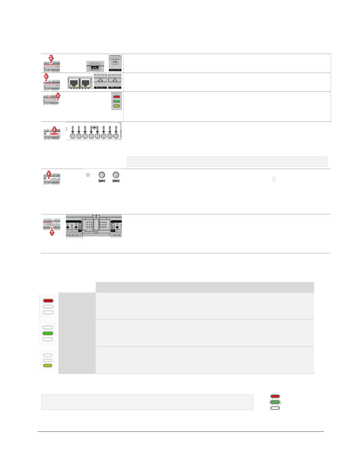
Indicator LEDs
(for LED signals see
CBXi Indicator LED Signals
on page 65)
Output Override (CBXi-8R8-H only)
Bottom position: Off - outputs forced off.
Centre position: Auto - outputs are controlled by strategy.
Top position: Manual - for digital outputs, the output is forced on. For analog
outputs the knob setting controls the output value.
Note: Manual position is supervised, i.e. the strategy is aware of the manual value.
Push buttons
Reset IP/Password : while the controller is
running
, press SW1 until the LED lights
up, then release SW1.
Full factory reset : while the controller is
booting
hold SW1 until the LED lights up,
then release SW1.
Restart the controller : while the controller is
running
, press SW2 until the LED lights up.
, then release SW2.
Inter-module connection sockets
To join the FLX bus, place the devices side-by-side and place the FLX bus
connector into the two adjacent sockets at once.
The end device on a FLX bus (either a FLX device or the CBXi itself) must have a
terminator inserted into its interconnector socket. One terminator is shipped
with each CBXi-8R8(-H) device.
CBXi INDICATOR LED SIGNALS
Strategy Loaded
but no network
connectivity
Strategy Loaded and
device communicating
on network
During firmware upgrade the Yellow LED will remain on while the strategy/comms section reboots, and
then the LEDs will rotate Red-Green-Yellow while the IO section reboots.
Note: During typical operation, the Red LED should be on, the Green LED should
be blinking and the Yellow LED should be off.