JOIN OR TERMINATE THE FLX BUS
Place the devices side-by-side and place the FLX bus connector into the two adjacent sockets at once.
The end device on a FLX bus (either a FLX device or the CBXi itself if no FLX devices are connected) must
have a terminator inserted into its interconnector socket. One terminator is shipped with each CBXi-
8R8(-H) device.
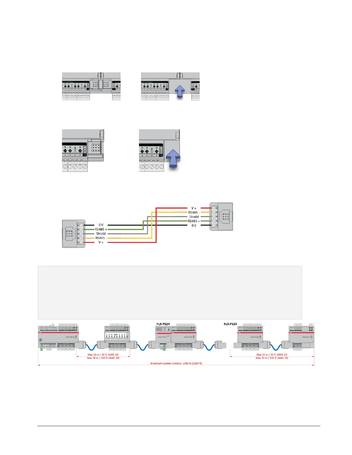
(IF REQUIRED) SET UP FLX BUS EXTENSION
If a FLX device cannot be located beside a CBXi device or another FLX device then The FLX bus can be
connected by cable using two FLX-RMC Remote Module Connectors, sold separately.
Connect cables to the two supplied FLX-RMC screw-terminal connectors as shown above with the
appropriate length of cable.
Note: Use Copper or Copper Clad Aluminum conductors only. Multiple wired connections can be used
between FLX modules, but the total FLX bus length must be less than 1200 m (3280 ft) for RS-485
communications.
Note: The total length of FLX bus segments powered by one source (CBX, CBXi or FLX-PS24) must not
exceed the following lengths:
Cable gauge Max length
AWG 18 30 m / 100 ft.
AWG 22 15 m / 50 ft.
If the RMC is connected to the Left-Hand side of a FLX-PS24, then it is not strictly necessary to connect
the 0 V and V+ lines: