Wiring with the logic relay
102
1SVC 440 795 M0100
Parameter display in RUN mode
Parameter display and parameter set for analog value
comparator in RUN mode with the display of the actual
values:
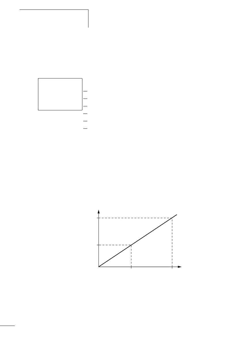
Resolution of the analog inputs
The analog inputs I7, I8, and on the CL-LMR/CL-LMT I11, I12
have the following resolution.
The analog signal from 0 to 10 V DC is converted to a 10-bit
digital value from 0 to 1023. A digital value of 100
represents an analog value of 1.0 V (exactly 0.98 V).
Figure 47: Resolution of the analog inputs
Actual value, e.g.: analog input
Factor is not used
Actual comparison value, e.g.: constant
Factor is not used
Offset is not used
The switching hysteresis is +/– 25
A1 EQ +
I1 0249 Æ
F1 0000
I2 0350 æ
F2 0000
OS 0000
HY 0025
U [V]
5.0
512
1023
10.0
0
 Loading...


