Installation
48
1SVC 440 795 M0100
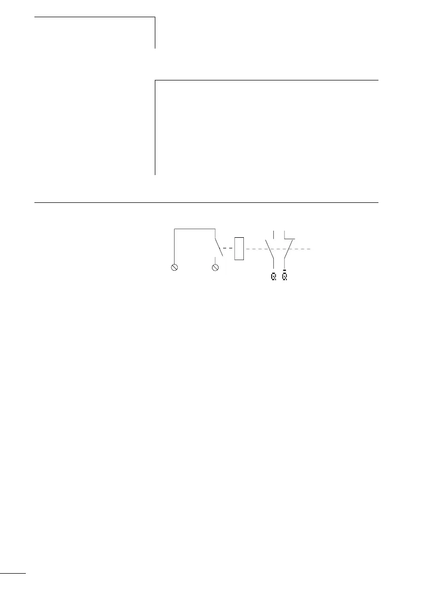
Connecting outputs The Q outputs operate inside the CL as isolated contacts.
Figure 26: Output Q
The associated relay coils are controlled in the CL circuit
diagram via the following outputs.
• Q1 to Q4 and Q1 to Q8 (Q6), basic units
• S1 to S8 (S6), expansion devices
The signal states of the outputs can be used in the CL circuit
diagram as n/o or n/c contacts for other switching
conditions.
The relay or transistor outputs are used to switch loads such
as fluorescent tubes, filament bulbs, contactors, relays or
motors. Prior to installation observe the technical limit
values and data for the outputs (a section “Technical
data”, Page 254).
h
Inputs that are used as high-speed counter inputs should
not be used in the circuit diagram as contacts. If the
counter frequency is high:
Not all the high-speed counter signals will be measured
for processing in the circuit diagram. The logic relay will
only process randomly detected signals in the circuit
diagram.
Q1
12
 Loading...


