Commissioning
60
1SVC 440 795 M0100
Creating your first circuit
diagram
The following single line diagram takes you step by step
through wiring up your first CL circuit diagram. In this way
you will learn all the rules, quickly enabling you to use the
logic relay for your own projects.
As with conventional wiring, you use contacts and relays in
the CL circuit diagram. With the logic relay, however, you no
longer have to connect up components individually. At the
push of a few buttons, the CL circuit diagram produces all
the wiring required. All you have to do is then connect any
switches, sensors, lamps or contactors you wish to use.
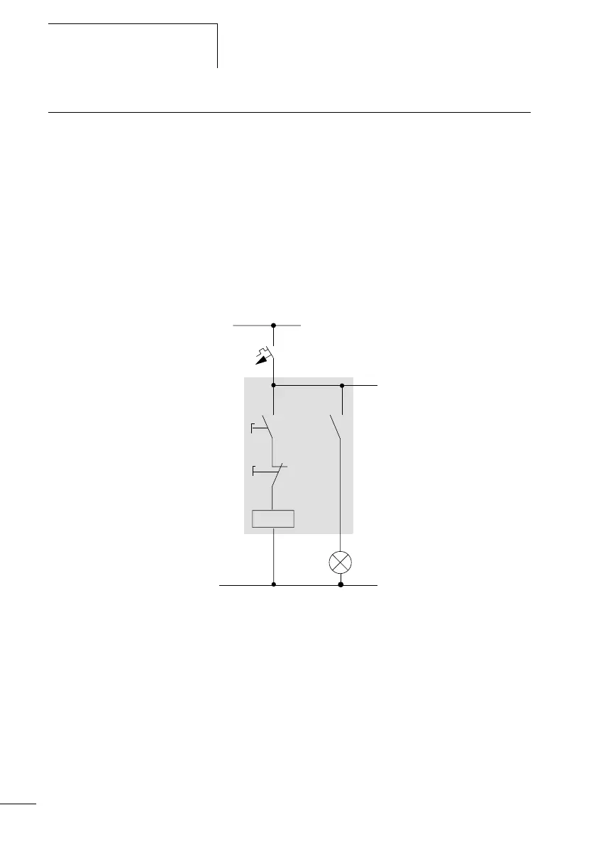
Figure 36: Lamp controller with relays
In the following example, the logic relay carries out all the
wiring and performs the tasks of the circuit diagram shown
below.
H1
L01-
S1
S2
L01+
F1
K1
K1
 Loading...


