What happens if …?
248
1SVC 440 795 M0100
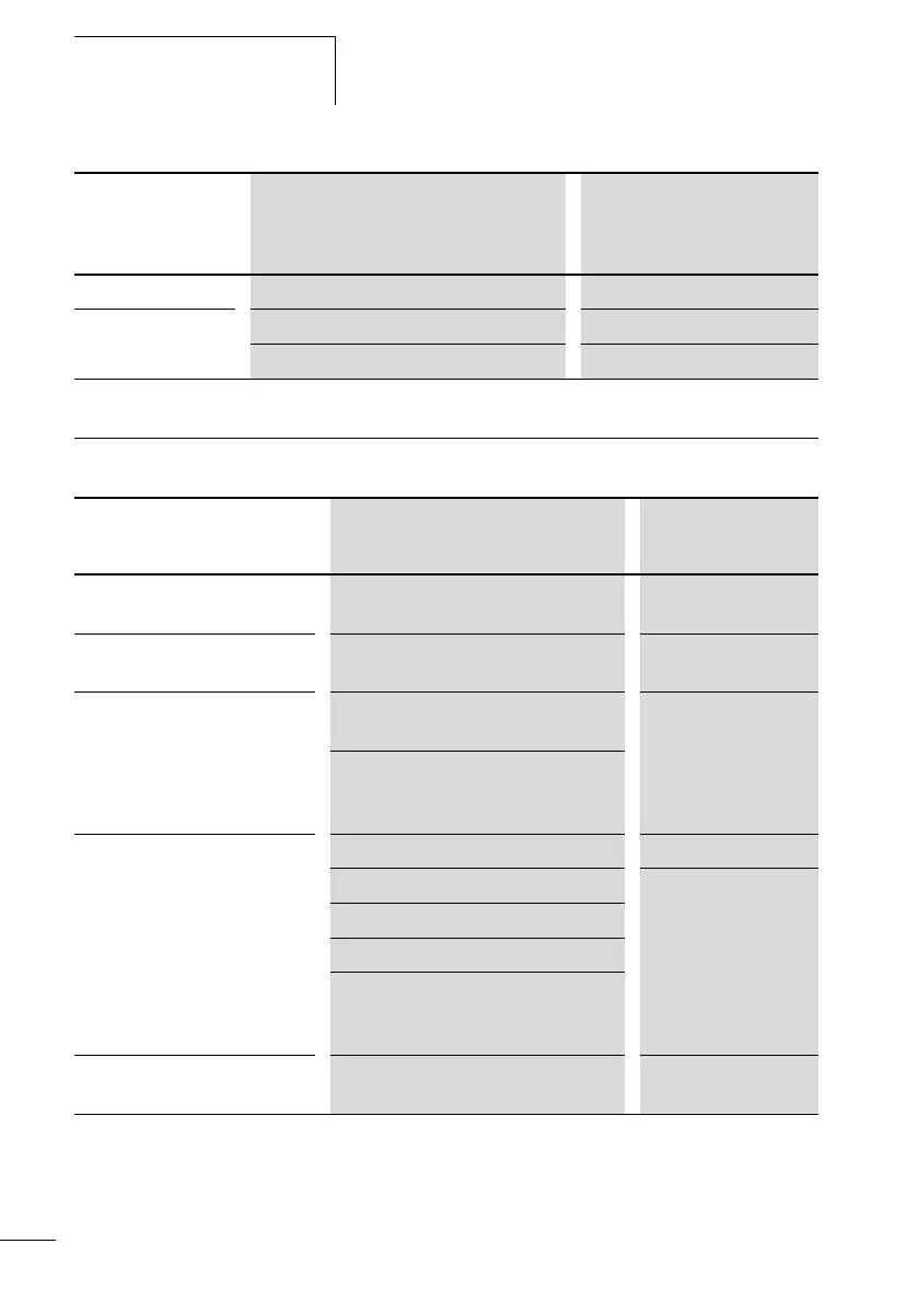
Possible situations when
creating circuit diagrams
ERROR: LCD LCD is faulty Replace logic relay
ERROR: ACLOW
Incorrect AC voltage Test the voltage
Logic relay is faulty Replace logic relay
Messages from
the CL system on
the LCD display
Explanation Remedy
Possible situations when
creating circuit diagrams
Explanation Remedy
Cannot enter contact or relay in
circuit diagram
Logic relay is in RUN mode Select STOP mode
Time switch switches at wrong
times
Time or time switch parameters not
correct
Check time and
parameters
Message when using a memory
module PROG INVALID
CL memory module without circuit
diagram
Change CL type or
change the circuit
diagram in the
memory module
Circuit diagram on the memory module
uses contacts/relays that the logic relay
does not recognise
Power flow display does not
show changes to the rungs
Logic relay is in STOP mode Select RUN mode
Association/connection not fulfilled Check and modify
circuit diagram and
parameter sets
Relay does not activate coil
Incorrect parameter values/time
• Analog value comparison is incorrect
• Time value of timing relay is incorrect
• Function of timing relay is incorrect
Relay Q or M does not energize
Relay coil has been wired up several
times
Check coil field entries
 Loading...


