Connecting the inputs
35
1SVC 440 795 M0100
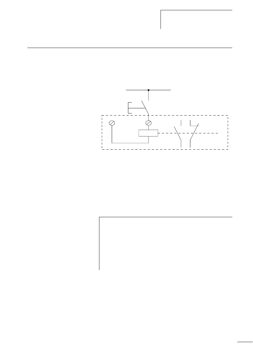
Connecting the inputs The inputs of the logic relay switch electronically. Once you
have connected a contact via an input terminal, you can
reuse it as a contact in your CL circuit diagram as often as
you like.
Figure 11: Connecting the inputs
Connect to the logic relay input terminals contacts such as
pushbuttons, switches, relay or contactor contacts, proximity
switches (three-wire).
Connect digital AC inputs
+24 V
S1
0 V
I1
I1 i1
L
N
i
Caution!
Connect the inputs for AC devices in compliance with the
safety regulations of the VDE, IEC, UL and CSA. The same
phase conductor to which the device power supply is
connected should be used for the supply of the inputs. The
logic relay will otherwise not detect the switching level or
may be destroyed by overvoltage.
 Loading...


