Wiring with the logic relay
154
1SVC 440 795 M0100
Function of the timing relay function block
Timing relay, on-delayed with and without random
switching
Random switching: The contact of the timing relay switches
randomly within the setpoint value range.
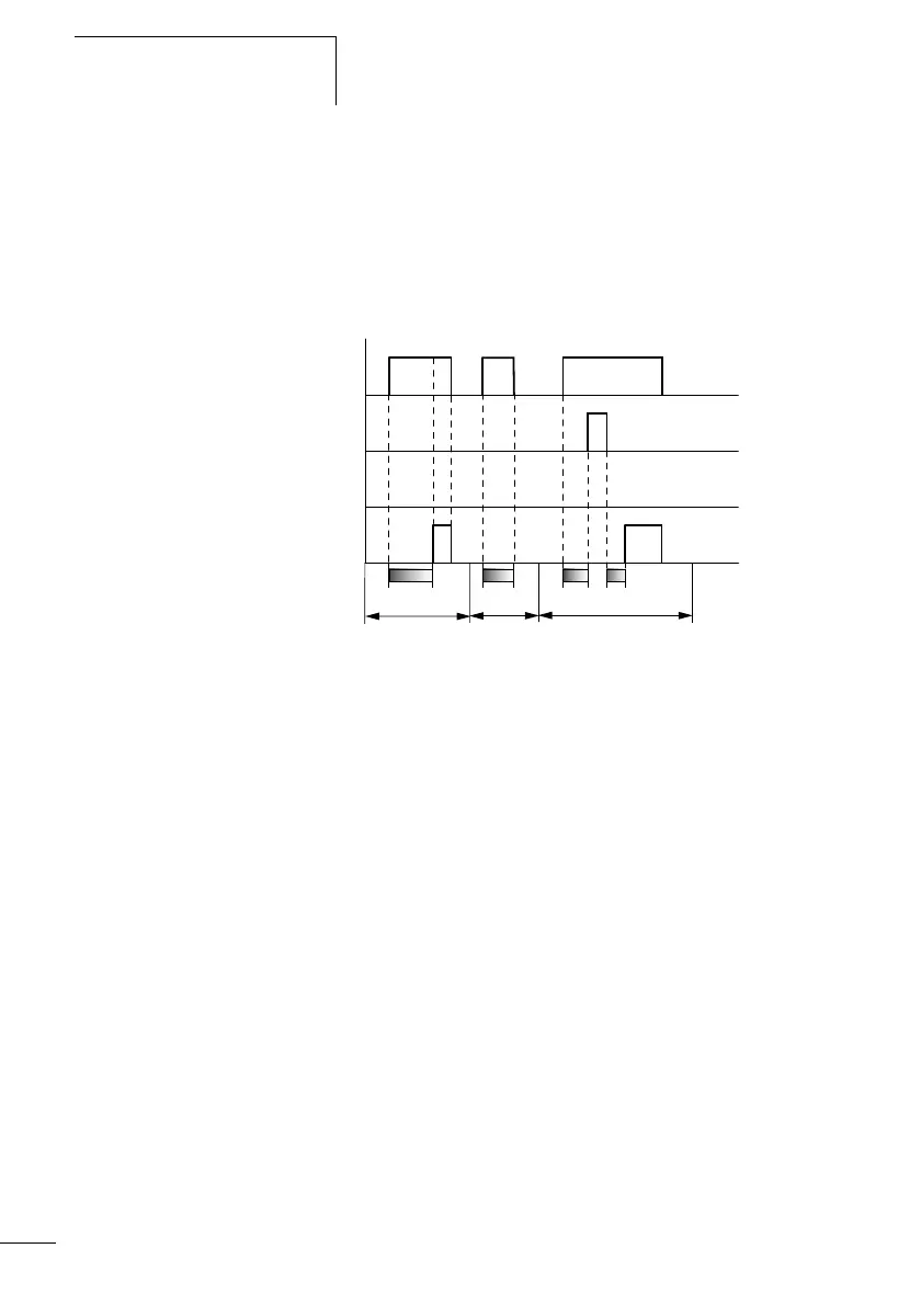
Figure 62: Signal diagram of timing relay, on-delayed
(with and without random switching)
1: Trigger coil TTx
2: Stop coil HTx
3: Reset coil RTx
4: Switching contact (n/o contact) Tx
t
s
: Setpoint time
• Range A: The set time elapses normally.
• Range B: The entered setpoint does not elapse normally because
the trigger coil drops out prematurely.
• Range C: The stop coil stops the time from elapsing.
t
1
+ t
2
= t
s
t
A
B
t
s
1
2
4
3
C
 Loading...


