Basic circuits
181
1SVC 440 795 M0100
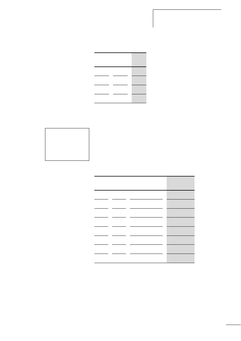
Table 21: Two-way circuit (XOR)
Self-latching
A combination of a series and parallel connection is used to
wire a latching circuit.
Latching is established by contact Q1 which is connected in
parallel to I1. If I1 is actuated and reopened, the current
flows via contact Q1 until I2 is actuated.
Table 22: Self-latching
Latching circuits are used to switch machines on and off. The
machine is switched on at the input terminals via n/o contact
S1 and is switched off via n/c contact S2.
S2 breaks the connection to the control voltage in order to
switch off the machine. This ensures that the machine can be
switched off, even in the event of a wire break. I2 is always
closed when not actuated.
I1 I2 Q1
000
01
1
101
110
I1uI2----ÄQ1
Q1k
S1 n/o contact at I1
S2 n/c contact at I2
I1 I2 Contact Q1
Coil Q1
000 0
010 0
100 0
110 1
001
0
011 1
101 0
111 1
 Loading...


