Year time switch
167
1SVC 440 795 M0100
Year time switch Types CL-LSR.C.../CL-LST.C... and CL-LMR.C.../CL-LMT.C...
are provided with a real-time clock that can be used as a
7-day time switch and year time switch in the circuit
diagram. If you have to implement special on and off
switching functions on public holidays, vacations, company
holidays, school holidays and special events, these can be
implemented easily with the year time switch.
The logic relay offers eight year time switches Y1 to Y8 for
up to 32 switch times.
Each time switch has four channels which you can use to set
four different on and off times. The channels are set via the
parameter display.
The time and date are backed up in the event of a power
supply failure and continue to run. This means that it will
continue to run in the event of a power failure, although the
time switch relays will not switch. When the device is in a
de-energized state, the timer contacts remain open. Refer to
section “Technical data”, Page 256, for information on the
buffer time.
Wiring of a year time switch
A year time switch can be integrated into your circuit in the
form of a contact.
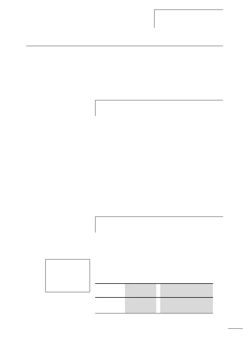
The coils and contacts have the following meanings:
h
The procedure for setting the time is described under
section “Setting date and time” on Page 205.
h
The clock module integrated in the logic relay works
within the date range 01.01.2000 to 31.12.2099.
Y1u------ÄQ1
Y2k
Ö1-Y3----ÄQ2
Contact Coil
Y1 to Y8 Contact of the year time
switch
 Loading...


