Wiring with the logic relay
112
1SVC 440 795 M0100
Wiring of a counter
You integrate a counter into your circuit in the form of a
contact and coil. The counter relay has different coils.
CL circuit diagram with counter relay
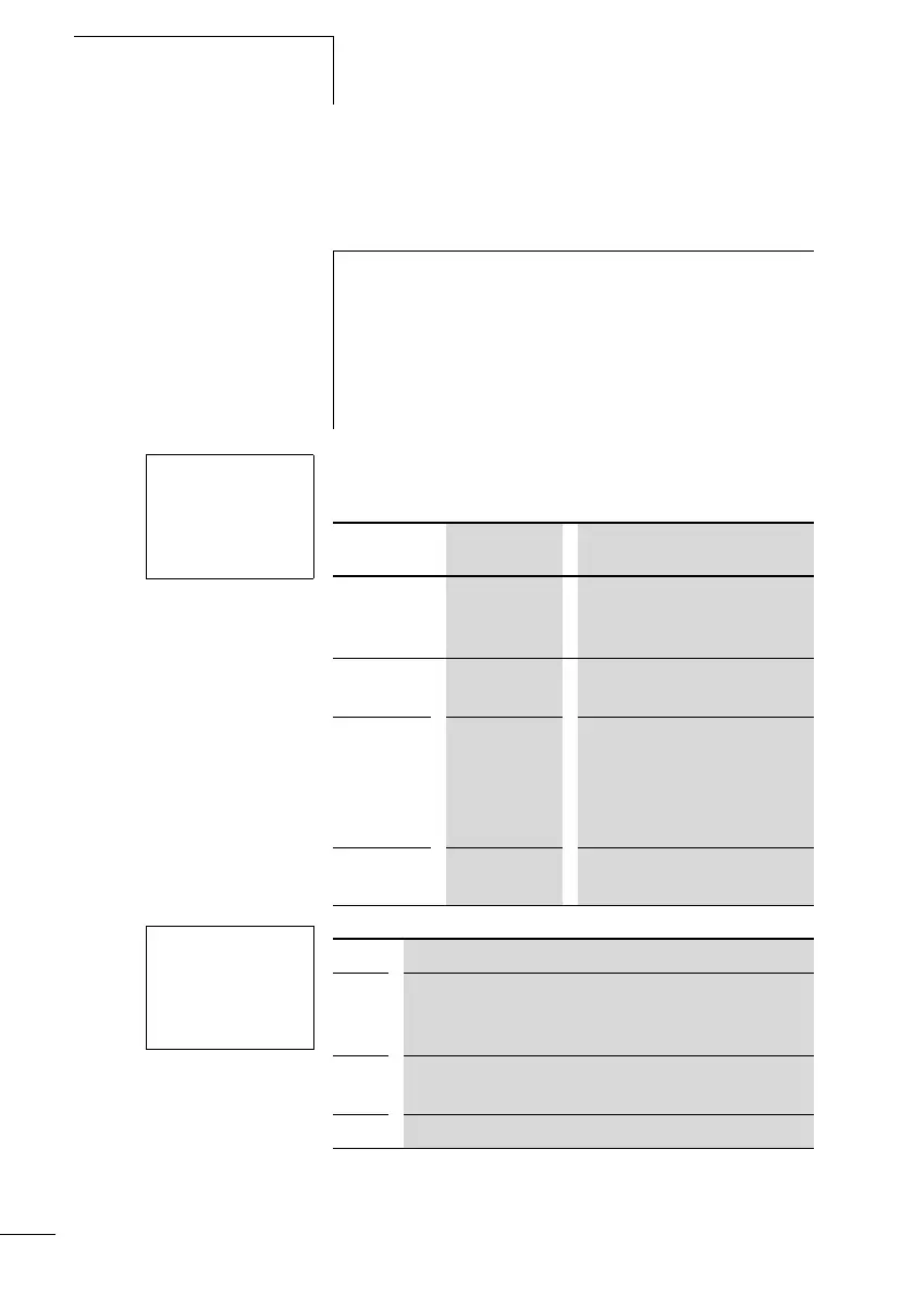
The coils and contacts have the following meanings:
Parameter display and parameter set for counter relays:
In the parameter display of a counter relay you change the
mode, the setpoint and the enable of the parameter display.
h
To prevent unpredictable switching states, use each coil of
a relay once only in the circuit diagram.
Do not use the input of a high-speed counter as a contact
in the circuit diagram. If the counter frequency is too high
only a random input value will be used in the circuit
diagram.
I5-------CC2
I6-------DC2
I7-------RC2
C2-------SM9
Contact Coil
C1 to C12 The contact switches if the
actual value is greater than or
equal to the setpoint.
CC1 to CC16 Counter input, rising edge
counts
DC1 to DC16 Counting direction
• Coil not triggered: up
counting.
• Coil triggered: down
counting.
RC1 to RC16 Reset, coil triggered: actual
value reset to 00000
C2 N +
S 00000
C2 Counter function relay number 2
N • Mode N: up/down counter
• Mode H: high-speed up/down counter
• Mode F: frequency counter
+ • + appears in the PARAMETER menu.
•
- does not appear in the PARAMETER menu
S Setpoint, constant from 00000 to 32000
 Loading...


