High-speed counters,
CL-DC1, CL-DC2
121
1SVC 440 795 M0100
You only integrate a frequency counter into your circuit in
the form of a contact and enable coil. The coils and contacts
have the following meanings:
Parameter display and parameter set for frequency
counter:
In the parameter display of a counter relay you change the
mode, the setpoint and the enable of the parameter display.
h
If you use C15 or C16 as frequency counters, coils DC15 or
DC16 will have no function. The counter signals are
transferred directly from the digital inputs I3 and I4 to the
counters. A frequency counter measures the actual value
and does not measure a direction.
---------CC
15
C
15
-------SQ3
I8--------
RC
15
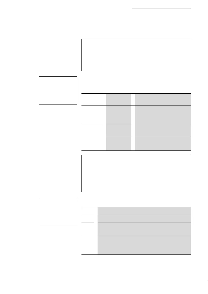
Contact Coil
C15 to C16 The contact switches if the
actual value is greater than or
equal to the setpoint.
CC15, CC16 Enable of the frequency counter
on “1” state, coil activated
RC15, RC16 Reset, coil triggered: actual
value reset to 00000
h
The frequency counter can also be enabled specifically for
a special operating state. This has the advantage that the
cycle time of the device is only burdened with the
frequency measurement when it is taking place. If the
frequency counter is not enabled, the cycle time of the
device is shorter.
C
15
F+
S 00200
C15 Counter function relay number 15
F Mode F: frequency counter
+ • + appears in the PARAMETER menu.
• - does not appear in the PARAMETER menu
S Setpoint, constant from 00000 to 01000
(32000 is a possible setting, the maximum frequency is
1 kHz)
 Loading...


