Wiring with the logic relay
88
1SVC 440 795 M0100
Display in the logic relay:
•Markers M, N:
èM1 to èM16, èN1 to èN16
•Jumps: è:1 to è:8
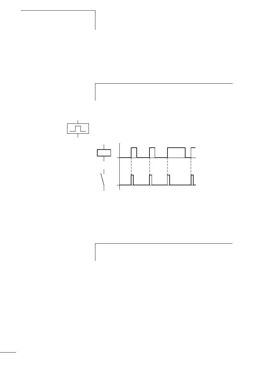
Rising edge evaluation (cycle pulse)
È
This function is used if the coil is only meant to switch on a
rising edge. With a change in the coil state from 0 to 1, the
coil switches its n/o contacts to the 1 state for one cycle.
Figure 42: Signal diagram of cycle pulse with rising edge
Display in the logic relay:
•Markers M, N:
ÈM1to ÈM16, ÈN1to ÈN16
•Jumps: È:1to È:8
h
Physical outputs should not be used as a cycle pulse is
generated.
on
on
h
Physical outputs should not be used as a cycle pulse is
generated.
 Loading...


