48 EL3000 CONTINUOUS GAS ANALYZERS | OI/EL3000-EN REV. D
… 5 Installation
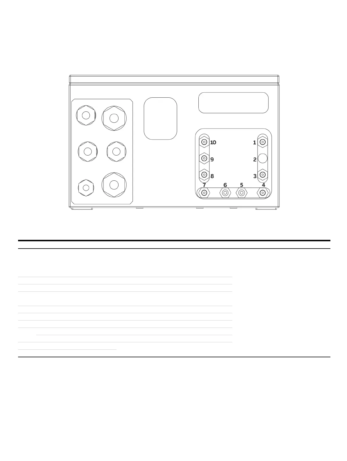
… Position and design of the gas connections
Gas connections Uras26 (model EL3040)
Figure 7: Gas connections Uras26 (model EL3040)
Uras26: Gas connections
Supplementary information
The pressure sensor is connected to the Pos. 1 terminal if
the internal gas lines are designed as stainless steel pipes,
or if the ‘Pressure sensor connected outside by hose’ option
is ordered.
⅛ NPT female thread (stainless steel 1.4305)
Connection of hose lines:
straight screw-in socket (PP) with
for hoses with inside diameter 4 mm (included
in scope of delivery)
Connection of piping:
screw-in fittings (not included in scope of
delivery)
—
Sample gas inlet (gas path
1) —
Sample gas outlet (gas path
1) For a measuring cell and for two measuring cells with
separate gas paths
Purge gas inlet (housing)
—
Purge gas outlet (housing)
—
Sample gas inlet (gas path
2) —
Sample gas outlet (gas path
2) —
Sample gas outlet (gas path 1)
For two sample cells in series
Sample cell 1 flowing reference gas
Note
• If the internal gas lines ares designed as hoses, the pressure sensor (standard, not for the ‘pressure sensor connected to outside
by hose’ option), and the oxygen sensor (option) are internally connected as follows:
– In the output of measuring cell 1, for one measuring cell and for two measuring cells with separate gas paths.
– In the output of measuring cell 2 for two measuring cells in a series.
– The second oxygen sensor (option for version with separate gas paths) is connected in the outlet of sample cell 2.
• If the internal gas lines are designed as stainless steel pipes, the oxygen sensor and the version with separated gas paths are not
possible.
 Loading...


