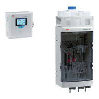
Navigator 500
Sodium analyzer 3 Installation
OI/ASO550–EN Rev. G 15
3.4.3 Wet-section PCB connections
Note.
Refer to Section 3.5.2, page 18, for connection details
at the transmitter.
Serial cable connections at each additional
wet-section are made into the same terminals IDs as
the factory-fitted serial cable.
Refer to Appendix C, page 78, for multiple
wet-section setup and serial connection details.
Fig. 3.12 Additional serial cable connections
to multiple wet-sections
Cable Color Ter mi na l I D Description
Serial
Red R 24 V
Black B 0 V
Green G Data +ve
White W Data –ve
Screen SCR Screen
Stream switch valve – single-stream
Red 1 Valve 1 +ve
Black 2 Valve 1 –ve
Stream switch valve – multi-stream
Green 1 Valve 1 +ve
Brown 2 Valve 1 –ve
Red 3 Valve 2 +ve
Black 4 Valve 2 –ve
Yellow 5 Valve 3 +ve
Orange 6 Valve 3 –ve
Table 3.1 Factory-made connections
B R
SCR
G W
Red – R (24 V)
Black – B (0 V)
Green – G (Data +ve)
White – W (Data –ve)
Screen – SCR
Cable Color Ter mi na l I D Description
Calibration valve
Green 7 Cal valve 1 +ve
Brown 8 Cal valve 1 –ve
Red 9 Cal valve 2 +ve
Black 10 Cal valve 2 –ve
Yellow 11 Regen valve +ve
Orange 12 Regen valve –ve
Reserved for pump (connection via separate PCB)
Red 14 +ve
Black 18 –ve
Flowmeter (if fitted)
Stream 1
Red 13 +ve
Brown 15 GND
Black 17 –ve
Stream 2 (multi-stream only)
Orange 20 +ve
Yellow 22 GND
Green 24 –ve
Stream 3 (multi-stream only)
Blue 19 +ve
Violet 21 GND
Grey 23 –ve
Pressure switch
Red 25 N/A
Black 26 N/A
Reference electrode
Black 32 N/A
Sodium electrode
Screen 34 N/A
Core 36 N/A
Pt1000 temperature sensor
Red 33 N/A
Blue 35 N/A
Table 3.1 Factory-made connections (Continued)

 Loading...