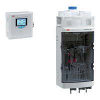
Navigator 500
Sodium analyzer 7 Menu descriptions
58 OI/ASO550–EN Rev. G
7.2 Analog sources and digital input / output sources
7.2.1 Analog sources
7.2.2 Digital output sources
7.2.3 Digital input sources
*(4) = maximum number of wet-sections if multiple wet-sections are connected.
Source name* Description
Low Level D. O. 1 (4)
Hydrazine 1 (4)
Sodium 1 (4)
Measured concentration value for the associated wet-section.
Sodium Stream 1 Measured concentration value for stream 1.
Sodium Stream 2 Sodium multi-stream: measured concentration value for stream 2.
Sodium Stream 3 Sodium multi-stream: measured concentration value for stream 3.
Temperature 1 (4) Measured temperature value for the associated wet-section.
Temperature 1 Sodium multi-stream: measured temperature value for stream 1.
Temperature 2 Sodium multi-stream: measured temperature value for stream 2.
Temperature 3 Sodium multi-stream: measured temperature value for stream 3.
Table 7.1 Analog sources
Source name* Description
Alarm 1 (8) State Process alarm state (alarm 1 to 8).
S1 (4) Failure The associated wet-section is in the failed state – see Appendix A, page 72 for possible causes.
S1 (4) Out of Spec. The associated wet-section is out of specification – see Appendix A, page 72 for possible causes.
S1 (4) Maintenance The associated wet-section requires maintenance – see Appendix A, page 72 for possible causes.
S1 (4) Function Check The associated wet-section requires checking – see Appendix A, page 72 for possible causes.
Tx Failure The transmitter is in the failed state – see Appendix A, page 72 for possible causes.
Tx Out of Spec. The transmitter is out of specification – see Appendix A, page 72 for possible causes.
Tx Maintenance The transmitter requires maintenance – see Appendix A, page 72 for possible causes.
Tx Function Check The transmitter requires checking – see Appendix A, page 72 for possible causes.
S1 (4) Cal in Progress A calibration is in progress for the associated wet-section.
S1 (4) Cal Failed The last calibration has failed for the associated wet-section.
Table 7.2 Digital output sources
Source name* Description
S1 (4) High Std Cal High standard calibrations.
S1 (4) Low Std Cal Low standard calibrations.
S1 (4) 2-Pt Cal Two-point calibrations.
S1 (4) 2-Regen Cal A sensor regeneration sequence is followed automatically by a two-point calibration.
S1 (4) Hold The measured concentration for the associated wet-section can be held via the digital input.
Note. It is recommended that a momentary switch is used to start or abort calibrations and a toggle switch is used for the hold
functionality.
To start a calibration – hold the momentary switch for a minimum of two seconds; when the calibration starts release the switch.
To abort a calibration – hold the momentary switch for a minimum of two seconds; when the calibration aborts release the switch.
Table 7.3 Digital input sources

 Loading...