If the PSTO input is used, connected to the Local-Remote switch on the local HMI, the choice
can also be from the station HMI system, typically ABB Microscada through IEC 61850–8–1
communication.
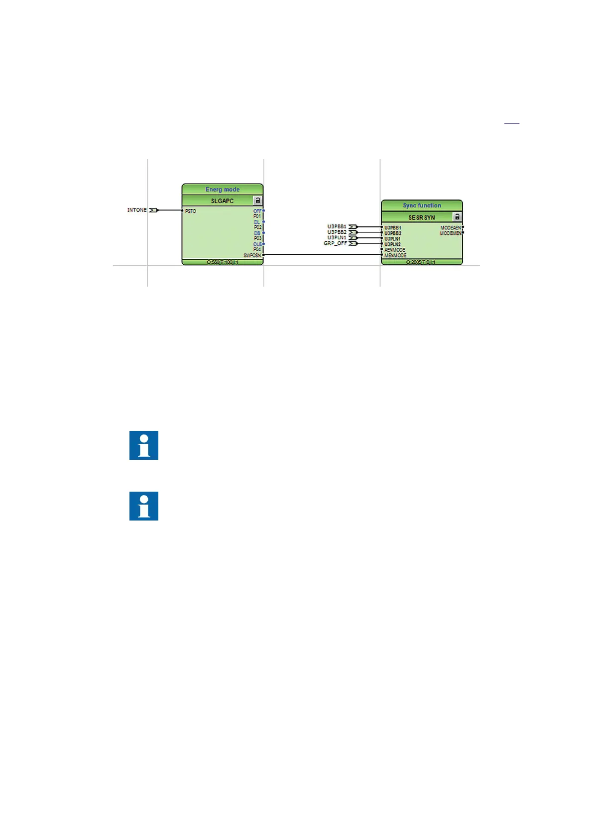
The connection example for selection of the manual energizing mode is shown in figure 124.
Selected names are just examples but note that the symbol on the local HMI can only show the
active position of the virtual selector.
IEC07000118 V3 EN-US
Figure 124: Selection of the energizing direction from a local HMI symbol through a
selector switch function block.
12.1.3 Application examples
M12323-3 v7
The synchronizing function block can also be used in some switchyard arrangements, but with
different parameter settings. Below are some examples of how different arrangements are
connected to the IED analogue inputs and to the function block SESRSYN. One function block
is used per circuit breaker.
The input used below in example are typical and can be changed by use of
configuration and signal matrix tools.
The SESRSYN and connected SMAI function block instances must have the
same cycle time in the application configuration.
Section 12 1MRK 505 370-UEN D
Control
254 Busbar protection REB670
Application manual

 Loading...


