GUID-C98D972D-D1D8-4734-B419-161DBC0DC97B V1 EN-US
Figure 34: Function button panel
The indication LED panel shows on request the alarm text labels for the indication LEDs. Three
indication LED pages are available.
GUID-5157100F-E8C0-4FAB-B979-FD4A971475E3 V1 EN-US
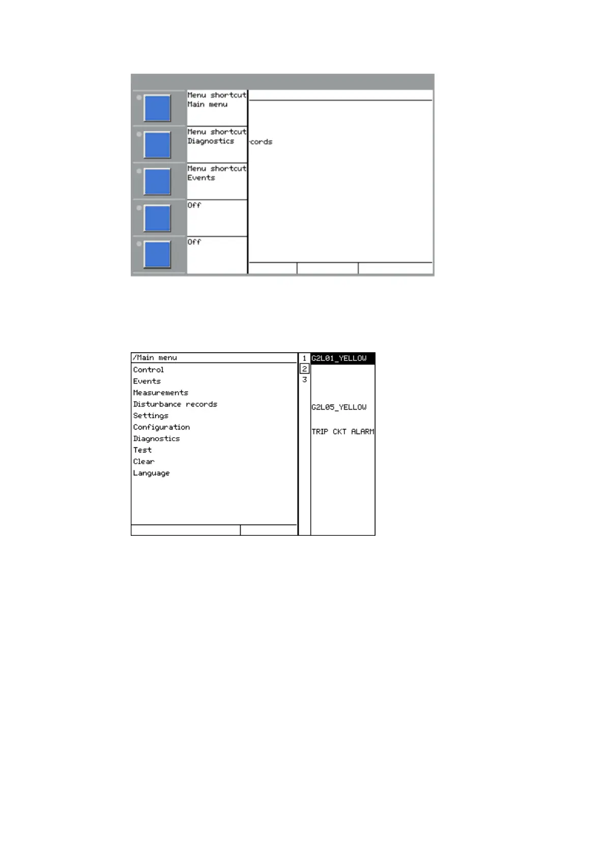
Figure 35: Indication LED panel
The function button and indication LED panels are not visible at the same time. Each panel is
shown by pressing one of the function buttons or the Multipage button. Pressing the ESC
button clears the panel from the display. Both panels have a dynamic width that depends on
the label string length.
5.2 LEDs
AMU0600427 v14
The LHMI includes three status LEDs above the display: Ready, Start and Trip.
There are 15 programmable indication LEDs on the front of the LHMI. Each LED can indicate
three states with the colors: green, yellow and red. The texts related to each three-color LED
are divided into three panels.
There are 3 separate panels of LEDs available. The 15 physical three-color LEDs in one LED
group can indicate 45 different signals. Altogether, 135 signals can be indicated since there are
1MRK 505 370-UEN D Section 5
Local HMI
Busbar protection REB670 85
Application manual

 Loading...


