IED
IE D
Protected zone
IEC05000442-2-en.vsdx
IEC05000442 V2 EN-US
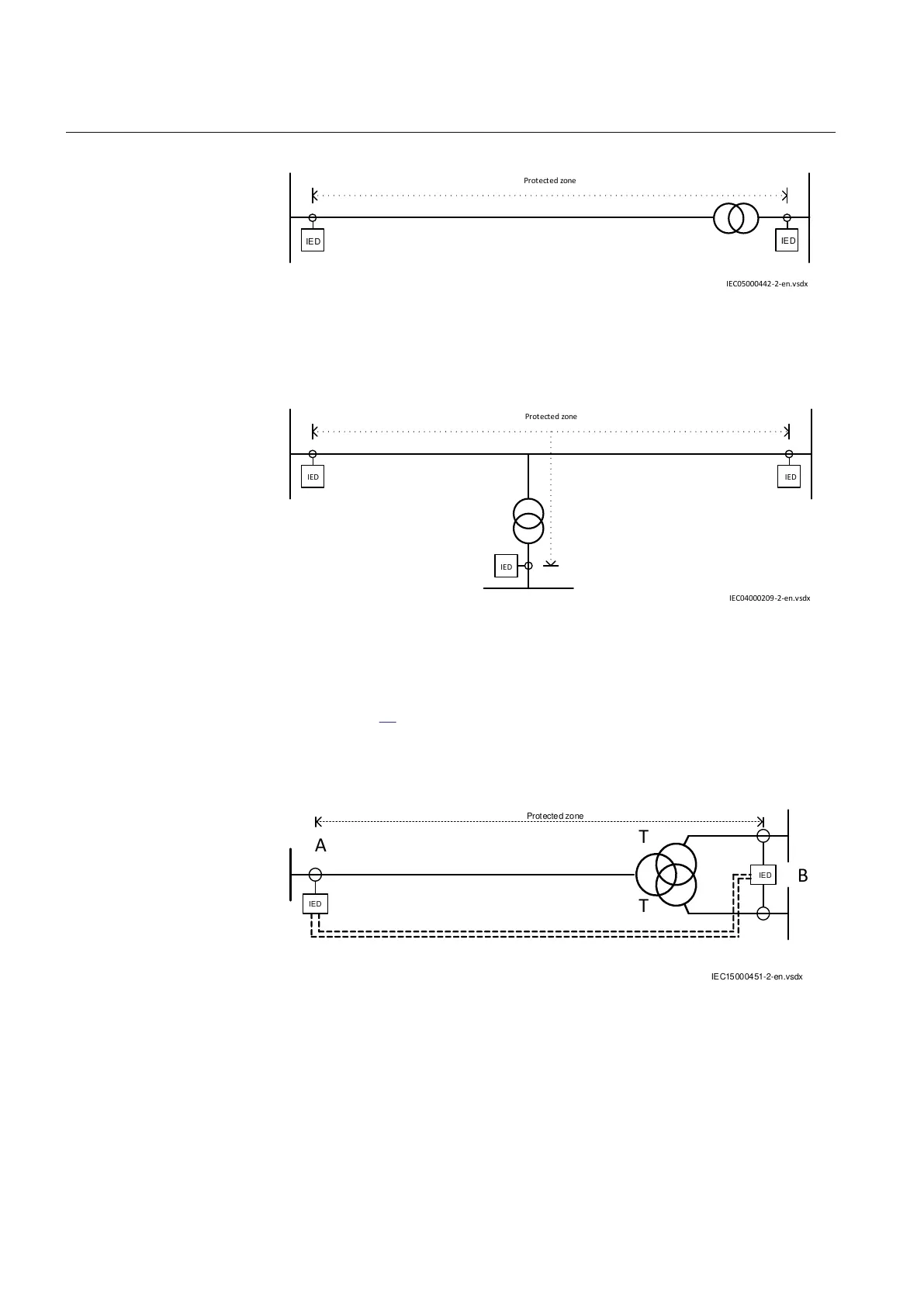
Figure 41: One two–winding transformer in the protected zone
IED
IED IED
Protected zone
IEC04000209-2-en.vsdx
IEC04000209 V2 EN-US
Figure 42: One two–winding transformer in the protected zone
Another alternative is with one three-winding transformer in the protected zone,
shown in Figure 43. Observe that in this case, the three-winding power transformer
is seen by the differential protection as two separate power transformers, A and B,
which have one common winding on the HV side.
IEC15000451-2-en.vsdx
IED
IED
A
B
T
T
Protected zone
IEC15000451 V2 EN-US
Figure 43: One three–winding transformer in the protected zone
TraAOnInpCh
M12541-239 v6
This parameter is used to indicate that a power transformer is included in the
protection zone at current terminal X. This can be either a two-winding transformer
Section 6 1MRK 505 393-UEN B
Differential protection
94 Line differential protection RED650 2.2 IEC
Application manual