99001019.vsd
~~
E
A
d
A
= const
d
B
= f(t)
E
B
A B
Z
SA
Z
SB
Z
L
R
IEC99001019 V1 EN-US
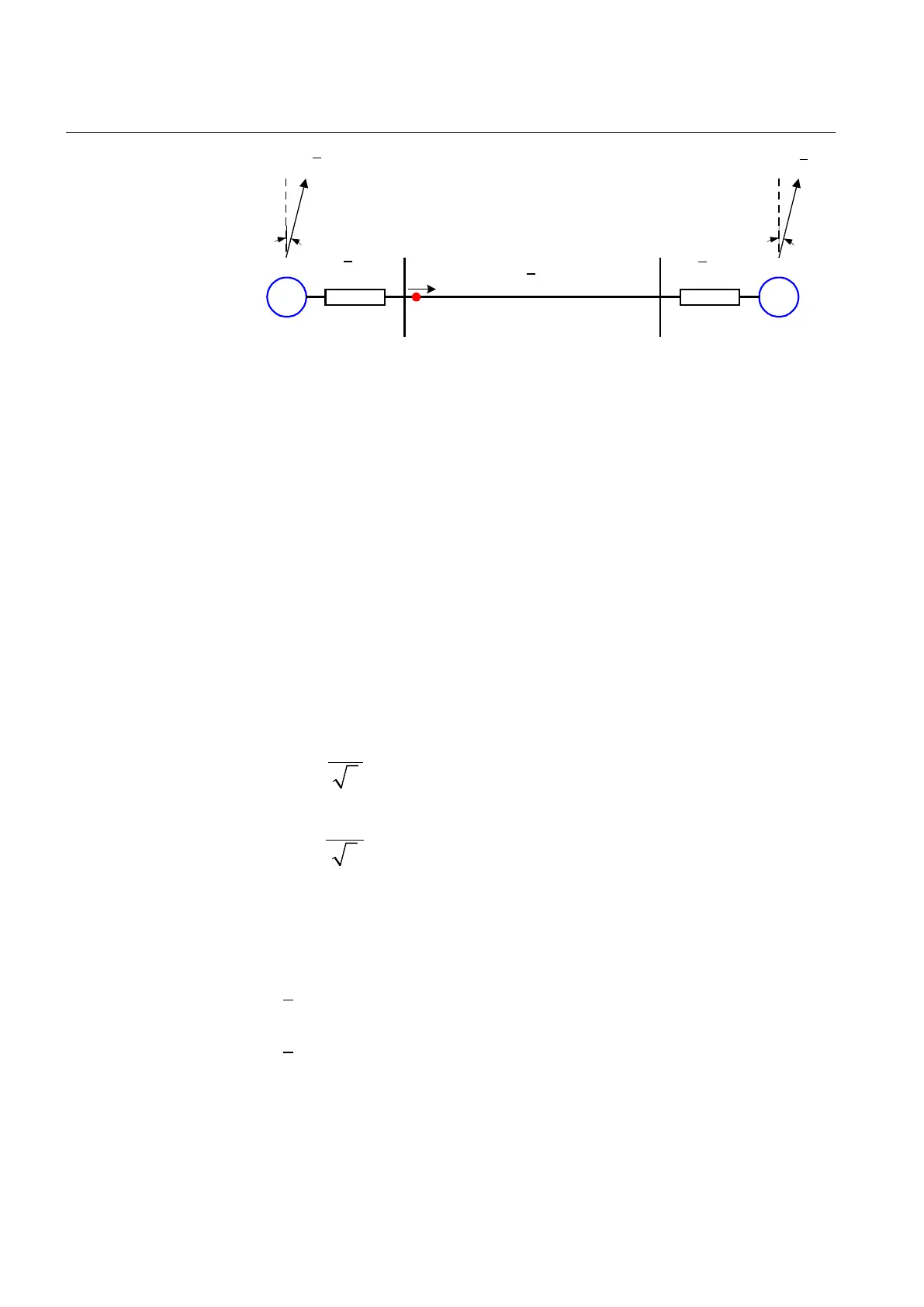
Figure 67: Protected power line as part of a two-machine system
Reduce the power system with protected power line into an equivalent two-
machine system with positive sequence source impedances Z
SA
behind the
protective relay R and Z
SB
behind the remote end bus B. Observe the fact that these
impedances cannot be directly calculated from the maximum three-phase short
circuit currents for faults on the corresponding busbar. It is necessary to consider
separate contributions of different connected circuits.
The required data is as follows:
EQUATION1321 V1 EN-US
Rated system voltage
EQUATION1322 V1 EN-US
Minimum expected system voltage under critical system
conditions
EQUATION1323 V1 EN-US
Rated system frequency
EQUATION1324 V1 EN-US
Rated primary voltage of voltage (or potential) transformers
used
EQUATION1325 V1 EN-US
Rated secondary voltage of voltage (or potential) transformers
used
EQUATION1326 V1 EN-US
Rated primary current of current transformers used
EQUATION1327 V1 EN-US
Rated secondary current of current transformers used
EQUATION1328 V1 EN-US
Positive sequence line impedance
EQUATION1329 V1 EN-US
Positive sequence source impedance behind A bus
Table continues on next page
Section 7 1MRK 505 393-UEN B
Impedance protection
136 Line differential protection RED650 2.2 IEC
Application manual
 Loading...


