A safety margin of 5% for the maximum static inaccuracy and a safety margin of
5% for maximum possible transient overreach have to be introduced. An additional
20% is suggested due to inaccuracy of instrument transformers under transient
conditions and inaccuracy in the system data.
The minimum primary current setting (Is) is:
EQUATION285 V3 EN-US (Equation 108)
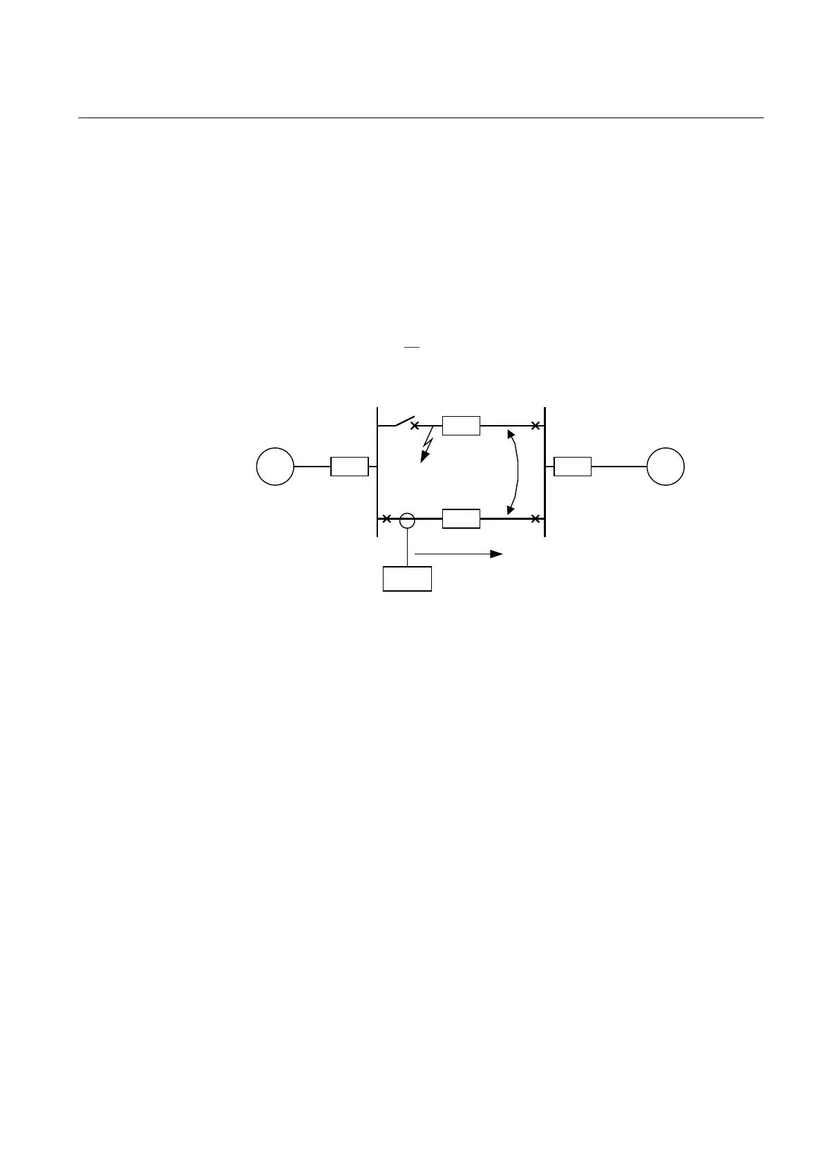
In case of parallel lines with zero sequence mutual coupling a fault on the parallel
line, as shown in Figure
80, should be calculated.
IEC09000025-1-en.vsd
~ ~
Z
A
Z
B
Z
L1
A B
I
M
Fault
IED
Z
L2
M
C
Line 1
Line 2
IEC09000025 V1 EN-US
Figure 80: Two parallel lines. Influence from parallel line to the through fault
current: I
M
The minimum theoretical current setting (Imin) will in this case be:
I m in M A X I
fA
I
fB
I
M
, ,( )³
EQUATION287 V1 EN-US (Equation 109)
Where:
I
fA
and I
fB
have been described for the single line case.
Considering the safety margins mentioned previously, the minimum setting (Is) is:
EQUATION288 V3 EN-US (Equation 110)
The IED setting value IN>> is given in percent of the primary base current value,
IBase. The value for IN>> is given by the formula:
1MRK 505 393-UEN B Section 8
Current protection
Line differential protection RED650 2.2 IEC 165
Application manual

 Loading...


