The bus and line frequencies must also be within a range of ±5 Hz from the
rated frequency. When the synchronizing option is included also for
autoreclose there is no reason to have different frequency setting for the
manual and automatic reclosing and the frequency difference values for
synchronism check should be kept low.
• The frequency rate of change is less than set value for both U-Bus and U-Line.
• The difference in the phase angle is smaller than the set value of
CloseAngleMax.
• The closing angle is decided by the calculation of slip frequency and required
pre-closing time.
The synchronizing function compensates for the measured slip frequency as well as
the circuit breaker closing delay. The phase angle advance is calculated
continuously. The calculation of the operation pulse sent in advance is using the
measured SlipFrequency and the set tBreaker time. To prevent incorrect closing
pulses, a maximum closing angle between bus and line is set with CloseAngleMax.
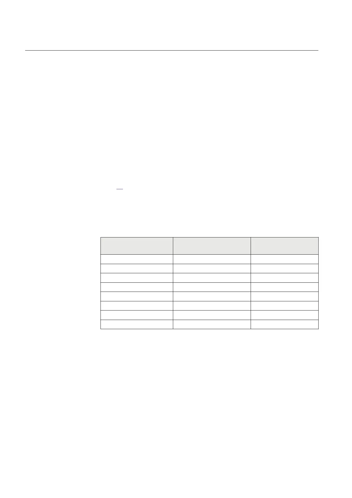
Table
19 below shows the maximum settable value for tBreaker when
CloseAngleMax is set to 15 or 30 degrees, at different allowed slip frequencies for
synchronizing. To minimize the moment stress when synchronizing near a power
station, a narrower limit for the CloseAngleMax needs to be used.
Table 19: Dependencies between tBreaker and SlipFrequency with different CloseAngleMax
values
tBreaker
[s] (max settable value)
with
CloseAngleMax
= 15
degrees [default value]
tBreaker
[s] (max settable value)
with
CloseAngleMax
= 30 degrees
[max value]
SlipFrequency [Hz]
(BusFrequency -
LineFrequency)
0.040
0.080 1.000
0.050 0.100 0.800
0.080 0.160 0.500
0.200 0.400 0.200
0.400 0.810 0.100
1.000 0.080
0.800 0.050
1.000 0.040
The reference voltage can be phase-neutral L1, L2, L3 or phase-phase L1-L2, L2-
L3, L3-L1 or positive sequence (Require a three phase voltage, that is UL1, UL2
and UL3) . By setting the phases used for SESRSYN, with the settings
SelPhaseBus1, SelPhaseBus2, SelPhaseLine2 and SelPhaseLine2, a compensation
is made automatically for the voltage amplitude difference and the phase angle
difference caused if different setting values are selected for the two sides of the
breaker. If needed an additional phase angle adjustment can be done for selected
line voltage with the PhaseShift setting.
Section 12 1MRK 505 393-UEN B
Control
216 Line differential protection RED650 2.2 IEC
Application manual
 Loading...


