A070702 V1 EN (Equation 3)
A situation when a phase A conductor is broken is shown in Figure 79
IECA070699 V1 EN
Figure 79: Broken conductor fault in phase A in a distribution or or
subtransmission feeder
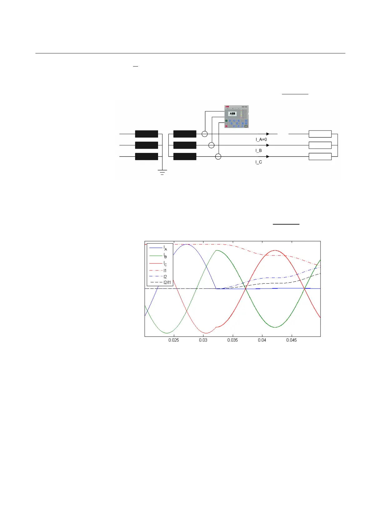
Current quantities during the broken fault in phase A, together with the ratio of
negative and positive sequence currents, are presented in
Figure 80
IECA070698 V1 EN
Figure 80: Three-phase currents, positive and negative sequence currents and
the ratio of sequence currents during broken conductor fault in phase
A
1MRS756378 D Section 5
Protection functions
REF615 161
Application Manual