2105552MNAE | RMC-100 | 13
The base holds the electronic board in its interior. Screws secure the board to the base, and the
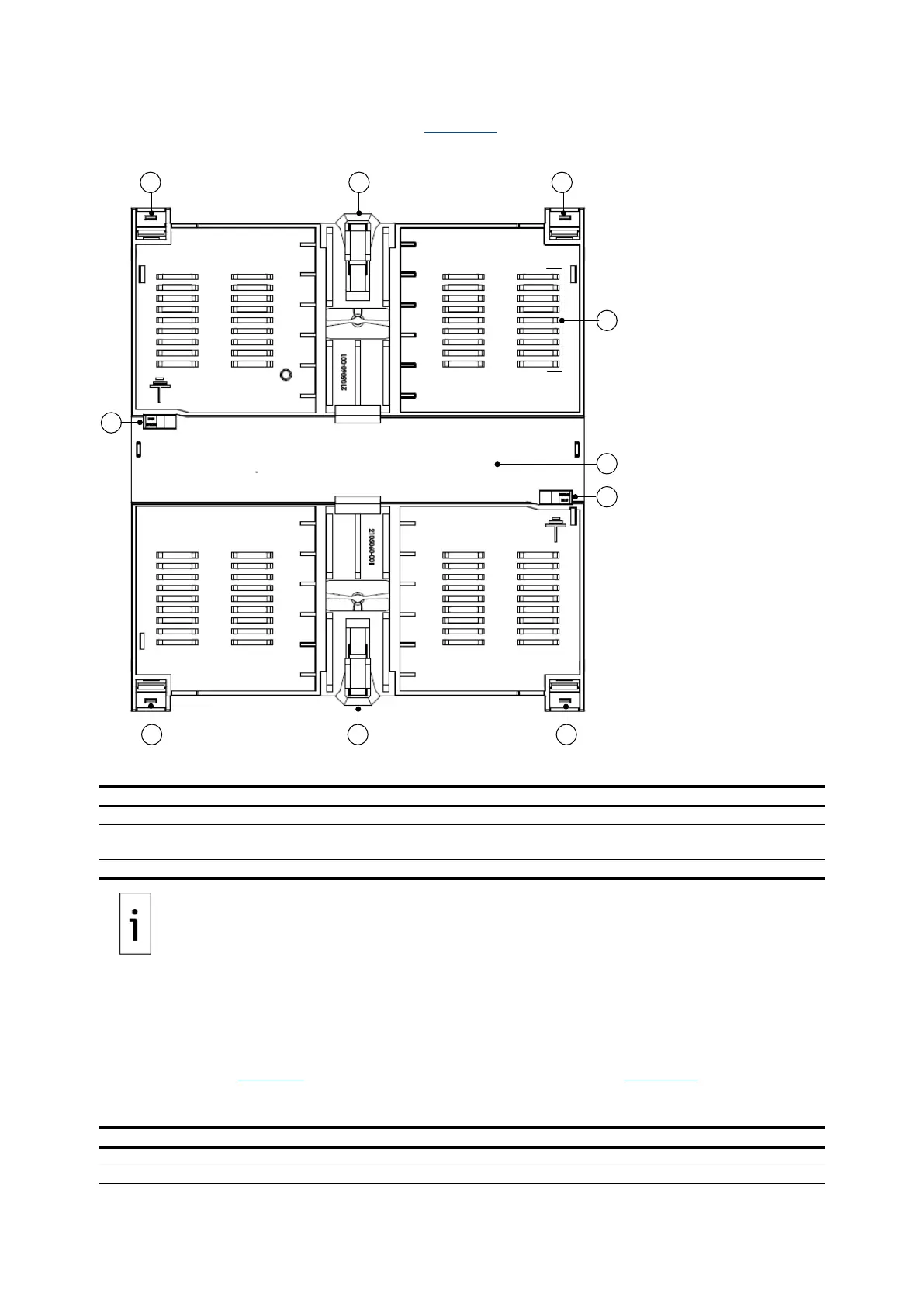
mounting clips are accessible on the exterior. Figure 2-2
identifies the exterior of the housing base.
Figure 2-2: RMC-100 housing base exterior
Legend for Figure 2-2: RMC-100 housing base exterior
Housing slot (secures top cover)
Spring release clip
(secures RMC to DIN rail)
Grounding slot
(for the electronic board grounding clips)
The RMC has grounding clips attached to the bottom of the electronic board.
The grounding clips fit through the base grounding slots to contact the DIN rail when mounted. Be
sure to
ground the DIN rail.
2.1.1 LCD display
The display assembly consists of the graphic LCD display and the directional buttons that navigate
through the display groups and associated variables. The display parameters are read-only.
The LCD size measures approximately 1⅝ x 2⅞ inches, with 128 x 64 pixels for display status and
configuration data. Table 2-1 provides the LCD display characteristics and Figure 2-3
shows the
display.
Table 2-1: LCD display characteristics
Number of lines on the display
Maximum number of characters per line

 Loading...


