180 System Manual SCK Gas Sampling System 42/23-81 EN Rev. 4
Step Procedure
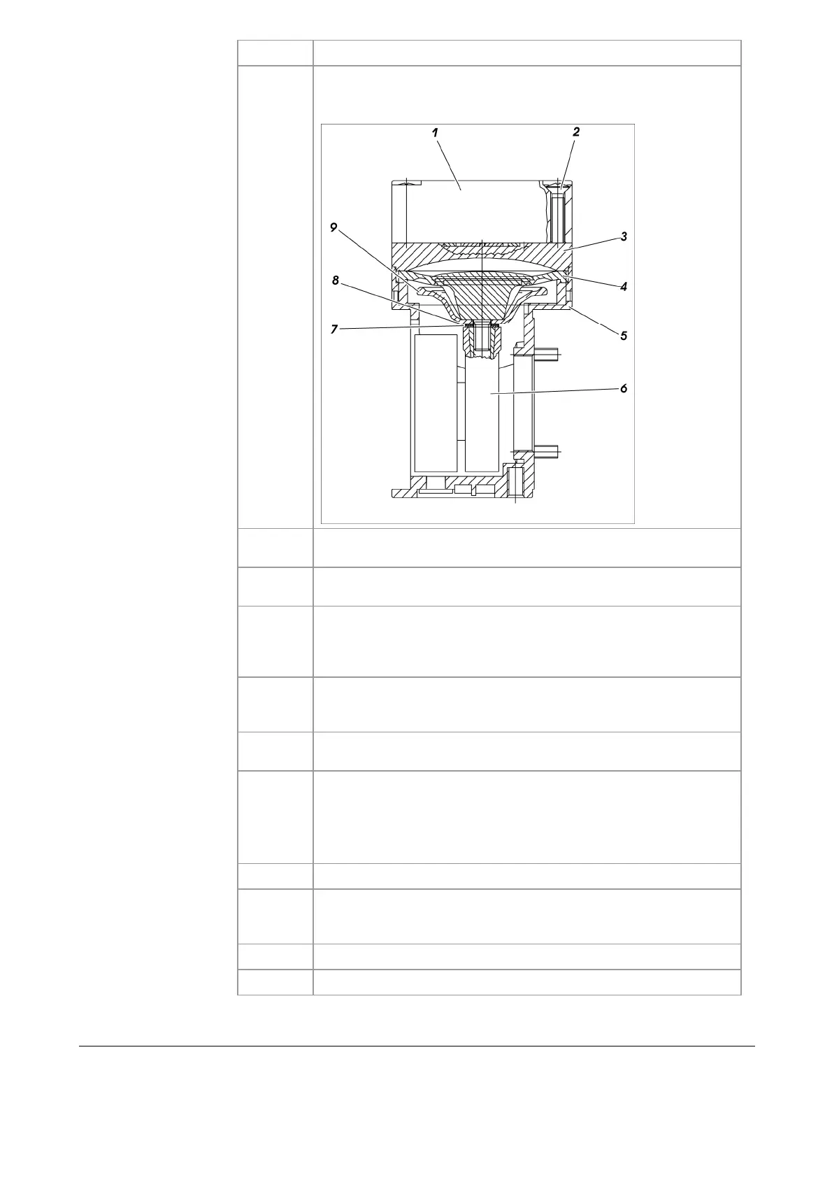
6
Mark the head cap (1), spacer plate (3) and housing (5) with a felt
pen. This prevents the possibility of these parts being fitted incor-
rectly when the pump is reassembled later.
7
Unscrew the four head-cover screws (2) and remove the head cap
along with the spacer plate from the pump housing.
8
Move the structural diaphragm by rotating the fan impeller to its
upper return point.
9
Lift the structural diaphragm (4) holding opposite sides and screw it
out counter-clockwise. Make sure that the cup spring (7) and the
adjusting washer(s) (8) do not fall off the threaded bolt of the struc-
tural diaphragm into the housing.
10
Remove the cup spring (7), adjusting washer(s) (8) and support
bowl (9) from the threaded bolt of the structural diaphragm and
store them.
11
Check all the parts for dirt and, if necessary, clean them with a dry
cloth or compressed air.
12
Push the support bowl (9), the adjusting washer(s) (8) and the cup
spring (7) onto the threaded bolt of the new structural diaphragm in
this order.
Note: The cup edge of the spring must face the structural dia-
phragm!
13
Move the connecting rod (6) to its upper return point.
14
Screw the new structure diaphragm with support bowl, adjusting
washer(s) and cup spring onto the connecting rod and tighten to
finger tightness.
15
Reconnect pump hoses.
16
Screw pump housing back on.